Service Manual
Page 1
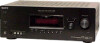
...and High-Definition Multimedia Interface are registered trademarks of HDMI Licensing LLC. The XM name and related logos are trademarks or registered trademarks of XM Satellite Radio Inc. SERVICE MANUAL Ver. 1.0 2007.03 STR-K7100 US Model Manufactured under the following conditions: Area code... frequency 87.5 - 108.0 MHz FM wire antenna 75 ohms, unbalanced 10.7 MHz - MULTI CHANNEL AV RECEIVER 9-887-608-01 2007C04-1 © 2007.03 Sony Corporation Home Audio Division Published by Sony Techno Create Corporation 1 Continued on the sound field settings and the source, there may be...
...and High-Definition Multimedia Interface are registered trademarks of HDMI Licensing LLC. The XM name and related logos are trademarks or registered trademarks of XM Satellite Radio Inc. SERVICE MANUAL Ver. 1.0 2007.03 STR-K7100 US Model Manufactured under the following conditions: Area code... frequency 87.5 - 108.0 MHz FM wire antenna 75 ohms, unbalanced 10.7 MHz - MULTI CHANNEL AV RECEIVER 9-887-608-01 2007C04-1 © 2007.03 Sony Corporation Home Audio Division Published by Sony Techno Create Corporation 1 Continued on the sound field settings and the source, there may be...
Service Manual
Page 4
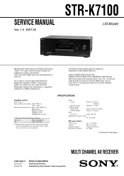
... Schematic Diagram - Schematic Diagram - Schematic Diagram - XM Section 35 5-22. Display Section 38 5-26. Chassis Section 58 7. STR-K7100 TABLE OF CONTENTS 1. GENERAL Description and location of parts 5 2. Front Panel Section 9 2-4. Printed Wiring Board - Printed Wiring Board...- Video Section 31 5-18. HDMI SW Section 33 5-20. Power Section 40 5-28. ELECTRICAL PARTS LIST 59 4 XM Section 19 5-7. Printed Wiring Boards - Digital Section (1/2 26 5-13. Case 8 2-2. STANDBY Board 11 3. Tuner/Audio Section 15 5-3. Block Diagram -...
... Schematic Diagram - Schematic Diagram - Schematic Diagram - XM Section 35 5-22. Display Section 38 5-26. Chassis Section 58 7. STR-K7100 TABLE OF CONTENTS 1. GENERAL Description and location of parts 5 2. Front Panel Section 9 2-4. Printed Wiring Board - Printed Wiring Board...- Video Section 31 5-18. HDMI SW Section 33 5-20. Power Section 40 5-28. ELECTRICAL PARTS LIST 59 4 XM Section 19 5-7. Printed Wiring Boards - Digital Section (1/2 26 5-13. Case 8 2-2. STANDBY Board 11 3. Tuner/Audio Section 15 5-3. Block Diagram -...
Service Manual
Page 6
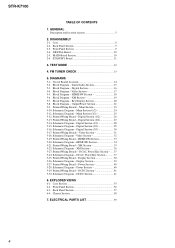
...?/1 (B) at the same time, it will turn on or off , press TV (Z) and then press AV ?/1. B COMPONENT VIDEO INPUT/ OUTPUT section Green Blue Red COMPONENT Connects to store a station. F ANTENNA section... to control non-Sony audio/video components. STR-K7100 Rear panel 1 2 DIGITAL (ASSIGNABLE) OPTICAL SAT IN VIDEO 2/ BD IN COAXIAL DVD IN DMPORT ANTENNA AM DVD IN VIDEO 2/BD IN OUT HDMI Y XM PB/... use the V/v/B/b and to a DVD IN jack player, etc. TUNING +/- select preset channels of the receiver, VCR, DVD player, satellite tuner, Blu-ray disc recorder, PSX, DVD/VHS COMBO...
...?/1 (B) at the same time, it will turn on or off , press TV (Z) and then press AV ?/1. B COMPONENT VIDEO INPUT/ OUTPUT section Green Blue Red COMPONENT Connects to store a station. F ANTENNA section... to control non-Sony audio/video components. STR-K7100 Rear panel 1 2 DIGITAL (ASSIGNABLE) OPTICAL SAT IN VIDEO 2/ BD IN COAXIAL DVD IN DMPORT ANTENNA AM DVD IN VIDEO 2/BD IN OUT HDMI Y XM PB/... use the V/v/B/b and to a DVD IN jack player, etc. TUNING +/- select preset channels of the receiver, VCR, DVD player, satellite tuner, Blu-ray disc recorder, PSX, DVD/VHS COMBO...
Service Manual
Page 31
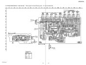
.... Location D203 D-8 D204 D-8 IC203 IC304 IC804 IC807 D-9 E-12 F-9 F-11 STR-K7100 31 31 No. VIDEO SECTION - • Refer to page 14 for Circuit Boards Location. : Uses unleaded solder. 1 2 3 4 5 6 7 8 9 10 11 A SAT IN J200...1 IN -4 -7 -5 -8 -6 -9 J302 MONITOR OUT -1 Y -2 PB/CB -3 PR/CR C D E VIDEO 3 BOARD J298 VIDEO 3 IN/PORTABLE AV IN R299 BLK C293 C294 F CN202 -1 VIDEO C299 -2 -3 L AUDIO R G (CHASSIS) H R298 C298 C312 R309 HDMI SW P BOARD CN5004 (Page 33) CN204 GRY 7 GRY GRY GRY GRY RED 1 DIGITAL L BOARD CNS510 (Page 27) C207 JW205...
.... Location D203 D-8 D204 D-8 IC203 IC304 IC804 IC807 D-9 E-12 F-9 F-11 STR-K7100 31 31 No. VIDEO SECTION - • Refer to page 14 for Circuit Boards Location. : Uses unleaded solder. 1 2 3 4 5 6 7 8 9 10 11 A SAT IN J200...1 IN -4 -7 -5 -8 -6 -9 J302 MONITOR OUT -1 Y -2 PB/CB -3 PR/CR C D E VIDEO 3 BOARD J298 VIDEO 3 IN/PORTABLE AV IN R299 BLK C293 C294 F CN202 -1 VIDEO C299 -2 -3 L AUDIO R G (CHASSIS) H R298 C298 C312 R309 HDMI SW P BOARD CN5004 (Page 33) CN204 GRY 7 GRY GRY GRY GRY RED 1 DIGITAL L BOARD CNS510 (Page 27) C207 JW205...
Service Manual
Page 32
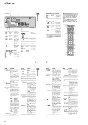
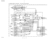
... L BOARD (2/3) CNS510 (Page 29) P HDMI SW BOARD CN5004 (Page 34) STR-K7100 STR-K7100 1 3 4 5 6 7 1 2 3 4 5 6 7 8 9 10 11 12 13 G V1 V2 1 V3 2 3 G 4 V1 V2 G 5-18. SCHEMATIC DIAGRAM - VIDEO SECTION - • Refer to page 44 for IC Block Diagrams. 1 2 3 4 5 6 VIDEO 3 BOARD J298 A 3P -1 V VIDEO CN201 5P 1 R-CH (Page 24) MAIN VIDEO 3 IN/ PORTABLE AV IN -2 L L C299 R299 2 GND...
... L BOARD (2/3) CNS510 (Page 29) P HDMI SW BOARD CN5004 (Page 34) STR-K7100 STR-K7100 1 3 4 5 6 7 1 2 3 4 5 6 7 8 9 10 11 12 13 G V1 V2 1 V3 2 3 G 4 V1 V2 G 5-18. SCHEMATIC DIAGRAM - VIDEO SECTION - • Refer to page 44 for IC Block Diagrams. 1 2 3 4 5 6 VIDEO 3 BOARD J298 A 3P -1 V VIDEO CN201 5P 1 R-CH (Page 24) MAIN VIDEO 3 IN/ PORTABLE AV IN -2 L L C299 R299 2 GND...
Service Manual
Page 50
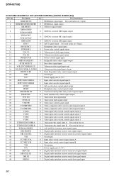
... reset signal output 38 DIR XMODE O Digital audio interface receiver reset signal output 39 DIR CLK SEL O Digital audio interface receiver serial clock select signal output 40 VSS - Pin Name I/O Pin Description 1 HDMI MUTE I HDMI mute signal input Not used in this set. (Open) 2 HDMI RESET/HDMI PRE O HDMI reset signal output 3 XM RESET O XM ...input (up) 16 VOL ENCODER(A) DOWN I Volume encoder signal input (down) 17 FRONT B RY O Front B speakers relay control signal output 18 GND - STR-K7100 IC1907 MB91353APMT-G-112E1 (SYSTEM CONTROL) (DIGITAL BOARD (2/3)) Pin No.
... reset signal output 38 DIR XMODE O Digital audio interface receiver reset signal output 39 DIR CLK SEL O Digital audio interface receiver serial clock select signal output 40 VSS - Pin Name I/O Pin Description 1 HDMI MUTE I HDMI mute signal input Not used in this set. (Open) 2 HDMI RESET/HDMI PRE O HDMI reset signal output 3 XM RESET O XM ...input (up) 16 VOL ENCODER(A) DOWN I Volume encoder signal input (down) 17 FRONT B RY O Front B speakers relay control signal output 18 GND - STR-K7100 IC1907 MB91353APMT-G-112E1 (SYSTEM CONTROL) (DIGITAL BOARD (2/3)) Pin No.
Service Manual
Page 51
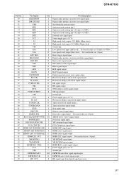
... IN I 88 HDMI CEC IN/HDMI OED I 89 HDMI UART IN/HDMI S1 I 90 HDMI UART OUT/HDMI S2 O 91 HDMI CEC OUT O 92 XM MIXMO I 93 XM MOXMI O 94 HDMI REG CTRL O 95 VCC I 96 VSS - 97 EEPROM DATA I/O 98 EEPROM CLK O 99 HD OUT I Pin Description Digital audio interface receiver error signal input Digital audio interface receiver state signal input...
... IN I 88 HDMI CEC IN/HDMI OED I 89 HDMI UART IN/HDMI S1 I 90 HDMI UART OUT/HDMI S2 O 91 HDMI CEC OUT O 92 XM MIXMO I 93 XM MOXMI O 94 HDMI REG CTRL O 95 VCC I 96 VSS - 97 EEPROM DATA I/O 98 EEPROM CLK O 99 HD OUT I Pin Description Digital audio interface receiver error signal input Digital audio interface receiver state signal input...


