Sony STR-K7100 Support Question
Sony STR-K7100 Support Question
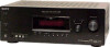
Find answers below for this question about Sony STR-K7100 - Multi Channel Av Receiver.Need a Sony STR-K7100 manual? We have 1 online manual for this item!
Question posted by Mmarkskw on March 21st, 2023
How To Use Room Setup Button On Remote
does this balance speakers and if so how do I do it.
Current Answers
Answer #1: Posted by SonuKumar on March 21st, 2023 11:28 PM
SonuKumar

Member since:
May 9th, 2021 Points: 16,609,790

Member since:
May 9th, 2021 Points: 16,609,790
The Room Setup button on the Sony STR-K7100 remote is used to set up the speakers and optimize the sound for your listening environment. Here's how to use it:
- Press the Room Setup button on the remote. The display on the receiver will show "AUTO CALIBRATION."
- Press the Enter button to start the auto calibration process.
- The receiver will emit test tones from each speaker in sequence, and the built-in microphone will pick up the sound and adjust the speaker settings accordingly.
- Once the calibration process is complete, the receiver will display the results on the screen, showing the speaker distances, levels, and other settings that have been optimized for your room.
- If you are not satisfied with the results or want to make manual adjustments, you can access the manual speaker settings from the receiver's on-screen menu.
Note: Before starting the auto calibration process, make sure that all the speakers are connected and properly positioned in your room. Also, ensure that the built-in microphone on the receiver is not obstructed and can pick up the test tones from each speaker accurately.
Please respond to my effort to provide you with the best possible solution by using the "Acceptable Solution" and/or the "Helpful" buttons when the answer has proven to be helpful.
Regards,
Sonu
Your search handyman for all e-support needs!!
Related Sony STR-K7100 Manual Pages
Service Manual - Page 1
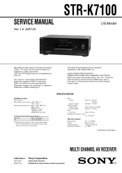
... - AUDIO POWER SPECIFICATIONS POWER OUTPUT AND TOTAL HARMONIC DISTORTION: With 6 ohm loads, both channels driven, from 250 milliwatts to rated output. SERVICE MANUAL
Ver. 1.0 2007.03
STR-K7100
US Model
Manufactured under the following conditions:
Area code US
Power requirements 120 V AC, 60 Hz
2) Reference power output for front, center and surround speakers. This receiver incorporates...
Service Manual - Page 3
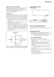
... Boards requiring use these instruments. 2.
The Data Precision 245 digital multimeter is suitable. A)
To Exposed Metal Parts on Chip Component Replacement • Never reuse a disconnected chip component. •...AC leakage.
The Simpson 250 and Sanwa SH-63Trd are suitable. (See Fig. STR-K7100
SAFETY CHECK-OUT (US MODEL) After correcting the original service problem, perform the ...
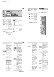
Service Manual - Page 5
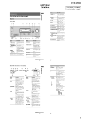
... status of the selected component or a list of parts
Receiver
Front panel
12
3
4 5 67
8
? / 1
SPEAKERS (OFF/A/B/A+B)
AUTO CAL MIC
PHONES
VIDEO 3 IN/PORTABLE AV IN
VIDEO
L AUDIO R
MULTI CHANNEL DECODING
DISPLAY
INPUT MODE
INPUT SELECTOR
MASTER VOLUME
MEMORY/ ENTER
TUNING MODE
TUNING
2CH
A.F.D. Press to select the input mode when the same components are connected to select...
Service Manual - Page 6
.... You can use the supplied remote to operate the receiver and to control the Sony audio/video components that the
remote is assigned to perform menu operations.
G AUTO CAL Press to select track
number 10.
- Press 0/10 to activate the Auto Calibration function. I MEMORY Press MEMORY to start playback of the buttons to select the component you press...
Service Manual - Page 7
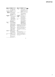
... operate differently than described. • The AUX on the remote is displayed on the component, the above explanation is also available for receiver operation.
13US
Getting Started
STR-K7100
7 Press to perform menu operations for XM Radio.
return to serve as references when operating the receiver.
b)The button is intended to the previous menu. - After pressing DVD...
Service Manual - Page 12
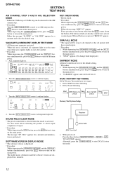
... Check
END
Factory Test System Setup
4.
The message "S.F. When this test is performed. ALL segments light on the main power. STR-K7100
SECTION 3 TEST MODE
AM CHANNEL STEP 9 kHz/10 kHz SELECTION MODE * Either the 9 kHz step or 10 kHz step can be swap to all channel so that all speaker will be selected for the...
Service Manual - Page 13
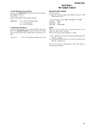
...the receiver and AUTO CAL microphone. The stop of test tone)
STR-K7100 SECTION 4 FM TUNER CHECK
FM AUTO STOP CHECK (1) Turn on the set. (2) Input the following signal from front left speaker of...Set to connect SG and the set. You cannot use SG whose output impedance is received in good condition."
13 DCAC board Checking Connect front left speaker, and the display will show : "DCAC[][][]x" ...
Service Manual - Page 20
... DATA 98 EEPROM CLK
FL_LAT 78 FL_DATA 71
FL_CLK 70
SIRCS IN 82
TUNER/AUDIO SECTION (Page 15)
F
C LINK RX C LINK TX
CNS504
9
8
FLASH...REMOTE CONTROL SIGNAL RECEIVER
IC103
2
RV102
3
MASTER VOLUME
F1
FL101
F2
VACUUM
FLUORESCENT
DISPLAY
LED DRIVER
Q110
D105
MULTI CHANNEL DECODING
2
RV101
3
INPUT SELECTOR
SW NETWORK S101-108
SW NETWORK S109-112,115
STR-K7100
20
20 STR-K7100...
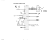
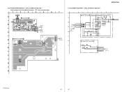
Service Manual - Page 21
...STR-K7100
STR-K7100
21
21 5-8.
L-CH R-CH R-CH
PRE DRIVER IC701
IN 2 8
PRE DRIVE
DRIVE
+VOUT2 -VOUT2 12
11
-45V +B
POWER AMP Q701-704
SL-CH
SR-CH R-CH
TUNER/
AUDIO... PHONES
TB001 (1/2)
L FRONT A
R
TM602
L FRONT B
R TB001 (2/2)
SPEAKERS
IMPEDANCE USE 6-16Ω
L
SURROUND R
TM604
CENTER
J309
AUDIO OUT
SUB WOOFER
T901
POWER
TRANSFORMER (MAIN)
• Signal path
: TUNER ...
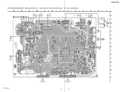
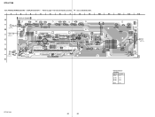
Service Manual - Page 23

.... STR-K7100
5-9. PRINTED WIRING BOARDS - MAIN SECTION - • Refer to page 14 for Circuit Boards Location.
1
2
3
4
5
6
7
: Uses unleaded solder.
8
9
10
11
12
13
14
A
TM602
SPEAKERS IMPEDANCE USE 6-16Ω
TB001
FRONT A
SURROUND
TM604 CENTER
L
L
L
J405
J403
J402
J309
FRONT B
R
R
R
SA-CD/CD/CD-R
TV
SAT
DVD
VIDEO 1
SUB WOOFER
OUT
IN
AUDIO IN
AUDIO IN...
Service Manual - Page 25

...330 2W
D691 1SS355WTE-17 6.5
Q692 DTA124ESA-TP
B- O P Y- M K
Q653 M N 2 4 8 8 - O P Y-
STR-K7100
5-11. SWITCH R699 470k
1
2
3
4
R693 10k
R694 10k
D802 D6SBN20-7003
RECT '
C803
6800 71V
'
C804 6800 71V
...LEF
RELAY DRIVER
0
64
R632 2.2k
D841 UDZSTE-173.0B
TM602 (+)
(-) (+)
(-)
TM602 SPEAKERS IMPEDANCE USE 6-16Ω L FRONT B
R
R840 6.8k C842 47 25V R844 R843 22k 0
...
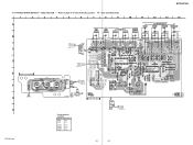
Service Manual - Page 26

...
R1466 C1568
R1411 R1410
C1408 C1405
C1567
I
R1077
FB1308
A2
X1101
R1179 R1180 R1088 R1073 R1072 R1181 R1182
LP1000
12 1-872-697- (12)
STR-K7100
26
26 STR-K7100
5-12. DIGITAL SECTION (1/2) - • Refer to page 14 for Circuit Boards Location.
: Uses unleaded solder.
1
2
3
4
5
6
7
8
9
10
11
12
13
A • Semiconductor
Location
DIGITAL BOARD (SIDE A)
Ref...
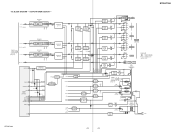
Service Manual - Page 27
DIGITAL SECTION (2/2) - • Refer to page 14 for Circuit Boards Location.
: Uses unleaded solder.
13
12
11
10
9
8
7
6
5
4
3
2
1
C
MAIN BOARD CNP913
(Page 23)
M
DISPLAY BOARD CNS100
(Page 38)
DIGITAL BOARD (SIDE B)...
C1403 R1409
R1353 R1352
B1
12
1-872-697- (12)
E F G H I
B
MAIN BOARD CN500
(Page 23)
A
MAIN BOARD CNP501
(Page 23)
STR-K7100
27
27 PRINTED WIRING BOARD...
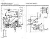
Service Manual - Page 31
... IC304 IC804 IC807
D-9 E-12 F-9 F-11
STR-K7100
31
31 STR-K7100
5-17. VIDEO SECTION - • Refer to page 14 for Circuit Boards Location.
: Uses unleaded solder.
1
2
3
4
5
6
7
8
9
10
11
A
SAT IN
J200
SAT
DVD
J201
-1
VIDEO 1
MONITOR
VIDEO IN
VIDEO IN
VIDEO OUT
VIDEO IN
VIDEO OUT
-2
-1
-2
-3
-1
-2
-3
B
12
13
14
J301 COMPONENT VIDEO
DVD IN
VIDEO 1 IN...
Service Manual - Page 37
... 10k
J2000 AUTO CAL MIC
POWER KEY BOARD
S115
D
SPEAKERS
CN103
R111 680
5P
S100
1 AD1
/
2 PW_SW
DISPLAY
3 GND
R BOARD
CN104
4 TUNING-JOG-A
(Page 39)
5 TUNING-JOG-B
H
STR-K7100
37
37 DCAC, POWER KEY SECTION -
• Refer to page 14 for Circuit Boards Location.
: Uses unleaded solder.
1
2
3
4
5
6
7
J2000 AUTO CAL MIC
A
DCAC BOARD
A001...
Service Manual - Page 38
... JW149
5
2
Q110 BE
S104 DISPLAY
JW111 R122 R131
D105 MULTI CHANNEL DECODING
R197
E
JW128 C164
JW132
10
11
12
13
14...DISPLAY SECTION - • Refer to page 14 for Circuit Boards Location.
1
2
3
4
5
6
7
: Uses unleaded solder.
8
9
DISPLAY BOARD
A
TP102
R110
DCAC
BOARD CN2000
Q
5
(Page 37)
CL201 CNP106
GRY
2...C-8
Q110
D-8
STR-K7100
38
38 No. STR-K7100
5-25.
Service Manual - Page 39
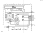
...GRID7
SEG8 21 -12.5 7P
SEG7 20
REMOTE CONTROL SIGNAL RECEIVER
6G -18.2
-6.9
6P
123
D
37...TC74ACT08P
BUFFER
Q110
D105
F
2SC1740S-QRT SELK5E20C-DTP15
LED DRIVER
M U LT I
CHANNEL
DECODING
5
3
5
0
1
2
3
4
5
6
7
5
0
R115 ...MUSIC
DISPLAY INPUT MODE AUTO CAL
MUTING
MEMORY/ENTER TUNING
-
+
MODE
TUNING
STR-K7100
39
39
CL029 CL028 CL030
CN108 3P
1 3 4
F1 F2 -20V
MAIN...
Service Manual - Page 40
...R811 0.22 1/2W
D
MAIN
I
5
1 CNP903
MAIN BOARD CN915
(Page 23)
GRY GRY GRY GRY ORG
N
DIGITAL BOARD CNP505 1-5
(Page 27)
STR-K7100
40
5-28. TA 2 B 5 D 9 1 11 0 E D B 4 0 - TA 2 B 5
D 9 1 31 0 E D ...NEUTRAL
AC IN '
40 POWER SECTION -
• Refer to page 14 for Circuit Boards Location.
: Uses unleaded solder.
1
2
3
4
5
6
7
A
STANDBY BOARD (CHASSIS)
B900
B
CL902
CL901
(...
Service Manual - Page 51
STR-K7100
Pin No.
Pin Name
I/O
49
DIR ERROR
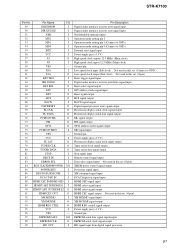
...clock) Not used in this set. (Connect to GND.) Low speed clock output (Sub clock) Not used in this set. (Open) Reset trigger signal input Digital audio interface receiver serial data... output Tuner serial data signal output Stop signal input Remote control signal input Error select signal input Not used in this set. (Open) XMDB power control signal...
Service Manual - Page 64
...CHIP 0
64
Description
CNS100 1-784-778-11 CONNECTOR, FFC 17P
Remark
< DIODE >
D105 6-501-539-01 LED SELK5E20C-DTP15 (MULTI CHANNEL DECODING)
< VACUUM FLUORESCENT DISPLAY >
FL101 1-519-927-11 VACUUM FLUORESCENT DISPLAY
< IC >
IC100 IC101 IC103
8-759-643-83... CARBON CARBON
10
5% 1/4W F
75
5% 1/4W
2.2K
5% 1/4W
2.7
5% 1/4W F
2.7
5% 1/4W F
Ref. STR-K7100
DISPLAY HDMI SW
Ref.
Similar Questions

How Do I Do A Hdmi Control On The Receiver?
I've been wondering how I can get my Insignia TV to know my Receiver. I've would use the RCA Monitor...
I've been wondering how I can get my Insignia TV to know my Receiver. I've would use the RCA Monitor...
(Posted by jaidenlawver10 1 year ago)

What Is The Remote Code For The Sony Str-k7100?
I have a universal remote and would like to use it with my sony str-k7100 but I do not know the remo...
I have a universal remote and would like to use it with my sony str-k7100 but I do not know the remo...
(Posted by navejaselijah6 1 year ago)

Sony Multi Channel Av Receiver Str-dg800
Where can I fond the ON/OFF power button for the Sony Multi Channel AV Receiver STR-DG800?
Where can I fond the ON/OFF power button for the Sony Multi Channel AV Receiver STR-DG800?
(Posted by denverliverpool 7 years ago)

How To Connect To Laptop Sony Multi Channel Av Receiver Str-k7100
(Posted by Tiadrober 9 years ago)

Multi Channel Av Receiver Str-ks2000
I Need A Sur L Cable
Where can i get that?Its a blue-headed cable.
Where can i get that?Its a blue-headed cable.
(Posted by MOKP94 12 years ago)