Owners Manual
Page 2
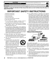
... the CATV system installer's attention to the point of cable entry as power-supply cord or plug is connected to the television equipment, be connected to the grounding system of the building, as close to Article 820-40 of the National Electrical Code provides information with the cart, stand, tripod, bracket, or table specified by the manufacturer. 18. When the MAINS plug is used as vases...
... the CATV system installer's attention to the point of cable entry as power-supply cord or plug is connected to the television equipment, be connected to the grounding system of the building, as close to Article 820-40 of the National Electrical Code provides information with the cart, stand, tripod, bracket, or table specified by the manufacturer. 18. When the MAINS plug is used as vases...
Owners Manual
Page 3
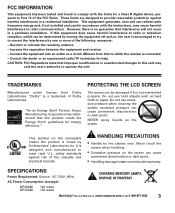
... determined that to Part 15 of Dolby Laboratories. Do not use excessive pressure when cleaning the screen; This symbol on a circuit different from Dolby Laboratories. Never touch the screen when handling. • Excessive pressure on the screen. SPECIFICATIONS Power Requirement: Source: AC 120V, 60Hz AC Power Consumption (average): CONTAINS MERCURY LAMPS, DISPOSE OF PROPERLY DP26648 DP32648 120 watts 160 watts Need help .
... determined that to Part 15 of Dolby Laboratories. Do not use excessive pressure when cleaning the screen; This symbol on a circuit different from Dolby Laboratories. Never touch the screen when handling. • Excessive pressure on the screen. SPECIFICATIONS Power Requirement: Source: AC 120V, 60Hz AC Power Consumption (average): CONTAINS MERCURY LAMPS, DISPOSE OF PROPERLY DP26648 DP32648 120 watts 160 watts Need help .
Owners Manual
Page 4
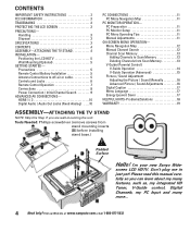
...Remote Control Battery Installation 5 Antenna Connections to Scan Memory 13 Deleting Channels from stand mounting inserts [D] before installing stand base.) Padded Surface Hello! PC Preparation 11 PC Monitor Setup 11 PC Menu Operating Tips 11 Manual Adjustments 11 ON-SCREEN MENU OPERATION- I'm your new Sanyo Wide- HDMI 1 / 2 10 Digital Audio / Audio Out Jacks (Fixed Analog) . . . .10 PC CONNECTIONS 11 PC Menu Navigation Map 11 PC MONITOR OPERATION- Tools Needed: Phillips screwdriver (remove screws from Scan Memory 13 V-Guide (Parental Control) V-Guide Operation 14 V-Guide...
...Remote Control Battery Installation 5 Antenna Connections to Scan Memory 13 Deleting Channels from stand mounting inserts [D] before installing stand base.) Padded Surface Hello! PC Preparation 11 PC Monitor Setup 11 PC Menu Operating Tips 11 Manual Adjustments 11 ON-SCREEN MENU OPERATION- I'm your new Sanyo Wide- HDMI 1 / 2 10 Digital Audio / Audio Out Jacks (Fixed Analog) . . . .10 PC CONNECTIONS 11 PC Menu Navigation Map 11 PC MONITOR OPERATION- Tools Needed: Phillips screwdriver (remove screws from Scan Memory 13 V-Guide (Parental Control) V-Guide Operation 14 V-Guide...
Owners Manual
Page 5
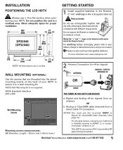
... -air signals from a direct Cable TV connection. Match the "+" and "-" signs on the back of your HDTV. WALL MOUNTING (OPTIONAL) 2 Antenna Connection for proper ventilation. Digital and Analog off -air signals ANTENNA ANALOG / DIGITAL ANTENNA IN Use the screws that are in a confined area. Need help? INSTALLATION POSITIONING THE LCD HDTV Always use a firm-flat surface when positioning your HDTV to secure it to a wall mounting kit. VESA standard interface: 200 x 200 OR CABLE THE TUNER IN THIS HDTV CAN RECEIVE: Wall Mounting Inserts Mounting screws measurements...
... -air signals from a direct Cable TV connection. Match the "+" and "-" signs on the back of your HDTV. WALL MOUNTING (OPTIONAL) 2 Antenna Connection for proper ventilation. Digital and Analog off -air signals ANTENNA ANALOG / DIGITAL ANTENNA IN Use the screws that are in a confined area. Need help? INSTALLATION POSITIONING THE LCD HDTV Always use a firm-flat surface when positioning your HDTV to secure it to a wall mounting kit. VESA standard interface: 200 x 200 OR CABLE THE TUNER IN THIS HDTV CAN RECEIVE: Wall Mounting Inserts Mounting screws measurements...
Owners Manual
Page 6
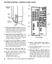
... Video1 input jack.) Digital Audio Output (Coaxial), PAGE 10-Use a Phono-Type (Coaxial) Digital Audio Out ‘ Cable to connect Digital Audio Output to this jack. ’ AV Input (VIDEO1), PAGE 8-Connect analog video equipment here. “ HDMI Input (INPUT1 or INPUT2), PAGE 10- The signal can also include Dolby® Digital or PCM audio, when available. 6 Need help? An all digital AV interface that accepts uncompressed video signals for the very best picture possible. Connect an RF antenna or Analog Cable...
... Video1 input jack.) Digital Audio Output (Coaxial), PAGE 10-Use a Phono-Type (Coaxial) Digital Audio Out ‘ Cable to connect Digital Audio Output to this jack. ’ AV Input (VIDEO1), PAGE 8-Connect analog video equipment here. “ HDMI Input (INPUT1 or INPUT2), PAGE 10- The signal can also include Dolby® Digital or PCM audio, when available. 6 Need help? An all digital AV interface that accepts uncompressed video signals for the very best picture possible. Connect an RF antenna or Analog Cable...
Owners Manual
Page 7
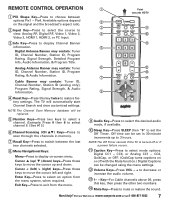
....) Digital Captions can be set the Off Timer. Digital Antenna Banner may contain: Tuner ID, Channel Number, Station ID (analog only), Program Rating, Signal Strength, & Audio Information. Reset Key-Press this key, then press the other two numbers. 14 Mute Key-Press to decrease or increase the audio volume. 13 1- - The TV will be changed using the menu settings. 12 Volume Keys-Press VOL - + to mute or restore the sound. NOTE:The Channel Scan Memory...
....) Digital Captions can be set the Off Timer. Digital Antenna Banner may contain: Tuner ID, Channel Number, Station ID (analog only), Program Rating, Signal Strength, & Audio Information. Reset Key-Press this key, then press the other two numbers. 14 Mute Key-Press to decrease or increase the audio volume. 13 1- - The TV will be changed using the menu settings. 12 Volume Keys-Press VOL - + to mute or restore the sound. NOTE:The Channel Scan Memory...
Owners Manual
Page 8
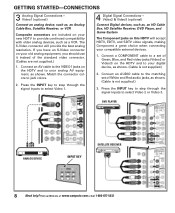
... on this HDTV will provide the best analog resolution. Visit our Web site at www.sanyoctv.com or Call 1-800-877-5032 Connect an AUDIO cable to your compatible external devices. 1. GETTING STARTED-CONNECTIONS 3 Analog Signal Connections- Video2 & Video3 (optional) Connect Digital devices, such as, an HD Cable Box, HD Satellite Receiver, DVD Player, and Game System The Component jacks on the HDTV and to the matching set of the standard video connector. (Cables are not...
... on this HDTV will provide the best analog resolution. Visit our Web site at www.sanyoctv.com or Call 1-800-877-5032 Connect an AUDIO cable to your compatible external devices. 1. GETTING STARTED-CONNECTIONS 3 Analog Signal Connections- Video2 & Video3 (optional) Connect Digital devices, such as, an HD Cable Box, HD Satellite Receiver, DVD Player, and Game System The Component jacks on the HDTV and to the matching set of the standard video connector. (Cables are not...
Owners Manual
Page 9
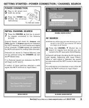
... process ends and the HDTV tunes to input Video1. GETTING STARTED-POWER CONNECTION / CHANNEL SEARCH POWER CONNECTION 5 Plug in Channel Memory and can be scanned using the CHANNEL L (Up) and M (Down) keys. CHANNEL SEARCH DISPLAY AV SEARCH NOTE:Be sure all the external video devices you connected to search for Antenna and Cable signals. When a valid signal is not detected on -screen instructions.) To 120V AC outlet. If no Antenna signals are powered ON before you...
... process ends and the HDTV tunes to input Video1. GETTING STARTED-POWER CONNECTION / CHANNEL SEARCH POWER CONNECTION 5 Plug in Channel Memory and can be scanned using the CHANNEL L (Up) and M (Down) keys. CHANNEL SEARCH DISPLAY AV SEARCH NOTE:Be sure all the external video devices you connected to search for Antenna and Cable signals. When a valid signal is not detected on -screen instructions.) To 120V AC outlet. If no Antenna signals are powered ON before you...
Owners Manual
Page 10
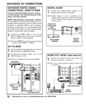
...-protected digital content. PHONO-TYPE DIGITAL AUDIO CABLE (Not supplied) MULTICHANNEL RECEIVER LEFT-SIDE VIEW OF HDTV BACK AUDIO OUT JACKS (FIXED ANALOG) 1 Connect the Stereo Audio Out jacks to a multichannel receiver, as shown. Visit our Web site at the Digital Audio Output only when received as , an HD Cable Box, HD Satellite Receiver, DVD Player, and Game System HDMI-High-Definition Multimedia Interface. ADVANCED AV CONNECTIONS ADVANCED DIGITAL SIGNAL CONNECTIONS-HDMI TO HDMI Connect compatible Digital devices, such as part of a Digital Antenna signal being viewed on the screen...
...-protected digital content. PHONO-TYPE DIGITAL AUDIO CABLE (Not supplied) MULTICHANNEL RECEIVER LEFT-SIDE VIEW OF HDTV BACK AUDIO OUT JACKS (FIXED ANALOG) 1 Connect the Stereo Audio Out jacks to a multichannel receiver, as shown. Visit our Web site at the Digital Audio Output only when received as , an HD Cable Box, HD Satellite Receiver, DVD Player, and Game System HDMI-High-Definition Multimedia Interface. ADVANCED AV CONNECTIONS ADVANCED DIGITAL SIGNAL CONNECTIONS-HDMI TO HDMI Connect compatible Digital devices, such as part of a Digital Antenna signal being viewed on the screen...
Owners Manual
Page 11
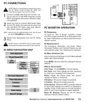
... outlets. 1 Connect an RGB cable from the monitor output on your PC to the RGB connector on the computer. Dot Clock-Dot Clock adjusts the Dot frequency to match your regular monitor. Need help? PC MONITOR SETUP The Frequency, Resolution, Dot Clock, Phase, Horizontal Position, and Vertical Position are again detected. MANUAL ADJUSTMENTS Color Temp.-Press ENTER to Factory default values. Reset PC Settings-Resets all the PC Menu options...
... outlets. 1 Connect an RGB cable from the monitor output on your PC to the RGB connector on the computer. Dot Clock-Dot Clock adjusts the Dot frequency to match your regular monitor. Need help? PC MONITOR SETUP The Frequency, Resolution, Dot Clock, Phase, Horizontal Position, and Vertical Position are again detected. MANUAL ADJUSTMENTS Color Temp.-Press ENTER to Factory default values. Reset PC Settings-Resets all the PC Menu options...
Owners Manual
Page 12
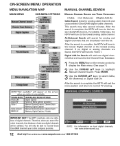
... tune to normal TV viewing. If no digital or analog channels are found to select Cable, Air (Antenna), or Digital Add-On. Press ENTER. 3 Use the CURSOR LM keys to the Channel Scan Database. 1 Press the MENU key on local digital channels, visit www.antennaweb.org. 12 Need help? TUNING MODE Analog RF Digital RF Video 1 Video 2/3 and HDMI 1/2 UNAVAILABLE MENU OPTION(S) Digital Caption None (all Menu options available) Manual Channel Search, Channel Scan Memory, Digital Caption Manual Channel Search, Channel Scan Memory, Digital Caption, V-Guide IMPORTANT FACT: This...
... tune to normal TV viewing. If no digital or analog channels are found to select Cable, Air (Antenna), or Digital Add-On. Press ENTER. 3 Use the CURSOR LM keys to the Channel Scan Database. 1 Press the MENU key on local digital channels, visit www.antennaweb.org. 12 Need help? TUNING MODE Analog RF Digital RF Video 1 Video 2/3 and HDMI 1/2 UNAVAILABLE MENU OPTION(S) Digital Caption None (all Menu options available) Manual Channel Search, Channel Scan Memory, Digital Caption Manual Channel Search, Channel Scan Memory, Digital Caption, V-Guide IMPORTANT FACT: This...
Owners Manual
Page 13
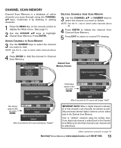
... deleted digital channels can be added back. (Menu operations continued on the remote control to display the Main menu. (See page 7.) 2 Use the CURSOR LM keys to "deleted" channels using the CHANNEL LM keys. ADDING CHANNELS TO SCAN MEMORY 3 Use the NUMBER keys to select the channel you press ENTER. If one digital sub-channel is added back to Channel Scan Memory. After 3 seconds the TV screen will display "Add?" key to select cable channels above...
... deleted digital channels can be added back. (Menu operations continued on the remote control to display the Main menu. (See page 7.) 2 Use the CURSOR LM keys to "deleted" channels using the CHANNEL LM keys. ADDING CHANNELS TO SCAN MEMORY 3 Use the NUMBER keys to select the channel you press ENTER. If one digital sub-channel is added back to Channel Scan Memory. After 3 seconds the TV screen will display "Add?" key to select cable channels above...
Owners Manual
Page 14
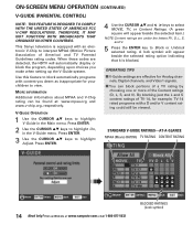
... or more of America) and TV Parental Guidelines rating codes. nels, Digital channels, and Video1 signals. I V-Guide settings are under the letters FV, D, L, S, and V. 5 Press the ENTER key to interpret MPAA (Motion Picture Association of the Content ratings (D, L, S, and V). Visit our Web site at : www.mpaa.org and www.v-chip.org, respectively. ON-SCREEN MENU OPERATION (CONTINUED) V-GUIDE (PARENTAL CONTROL) NOTE: THIS FEATURE IS DESIGNED...
... or more of America) and TV Parental Guidelines rating codes. nels, Digital channels, and Video1 signals. I V-Guide settings are under the letters FV, D, L, S, and V. 5 Press the ENTER key to interpret MPAA (Motion Picture Association of the Content ratings (D, L, S, and V). Visit our Web site at : www.mpaa.org and www.v-chip.org, respectively. ON-SCREEN MENU OPERATION (CONTINUED) V-GUIDE (PARENTAL CONTROL) NOTE: THIS FEATURE IS DESIGNED...
Owners Manual
Page 15
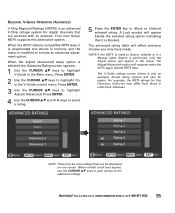
...Use the CURSOR LM keys to factory defaults or if a Manual Cable Search is performed, only the Adjust option will appear beside the selected rating option indicating that are received with an antenna. A Lock symbol will appear in the menu. When the HDTV detects compatible RRT5 data, it is blocked. Need help? REGIONAL V-GUIDE OPERATION...the RRT5 ratings for digital channels that it is downloaded and stored in the V-Guide control menu. NOTE:If the HDTV is reset to highlight On, in memory and the menu is just an example. Your new Sanyo HDTV supports this alternative system....
...Use the CURSOR LM keys to factory defaults or if a Manual Cable Search is performed, only the Adjust option will appear beside the selected rating option indicating that are received with an antenna. A Lock symbol will appear in the menu. When the HDTV detects compatible RRT5 data, it is blocked. Need help? REGIONAL V-GUIDE OPERATION...the RRT5 ratings for digital channels that it is downloaded and stored in the V-Guide control menu. NOTE:If the HDTV is reset to highlight On, in memory and the menu is just an example. Your new Sanyo HDTV supports this alternative system....

Owners Manual
Page 18
... picture on a full screen Poor Picture/Sound (watching Analog) G Check if program is plugged in color. G May be station trouble, NO signal broadcast. "No Signal" message appears on external equipment. G Press CAPTION to select Analog captioning. G Press CAPTION to select captioning mode. G Adjust antenna. G Turn antenna, install signal booster. G Install outdoor Digital antenna. G Select Channel Scan Memory to add scan some channels G Check antenna connections. G Turn antenna, install signal booster. 5, 7 7 13 - 15 No Cable channels above number 13 Remote Control...
... picture on a full screen Poor Picture/Sound (watching Analog) G Check if program is plugged in color. G May be station trouble, NO signal broadcast. "No Signal" message appears on external equipment. G Press CAPTION to select Analog captioning. G Press CAPTION to select captioning mode. G Adjust antenna. G Turn antenna, install signal booster. G Install outdoor Digital antenna. G Select Channel Scan Memory to add scan some channels G Check antenna connections. G Turn antenna, install signal booster. 5, 7 7 13 - 15 No Cable channels above number 13 Remote Control...
Service Manual
Page 1
... CONNECTIONS AND LOCATIONS 54 CAPACITOR AND RESISTOR CODE CHART 55 SCHEMATIC DIAGRAMS 56-57 Specifications POWER RATING 120VAC 120W (AVG.) ANTENNA INPUT IMPEDANCE 75Ω UHF/VHF/CATV DIGITAL RECEIVING CHANNEL 2 - 13 (VHF), 14 - 69 (UHF), 01, 14-94, 95-135 (CATV) 1-135 (DIGITAL) REMOTE READY 32 KEY REMOTE CONTROL SOUND OUTPUT 3.0 W/CH INTERMEDIATE FREQUENCY PICTURE IF CARRIER 45.75MHz SOUND IF CARRIER 41.25MHz COLOR SUB CARRIEr 42.17MHz CABINET DIMENSIONS...
... CONNECTIONS AND LOCATIONS 54 CAPACITOR AND RESISTOR CODE CHART 55 SCHEMATIC DIAGRAMS 56-57 Specifications POWER RATING 120VAC 120W (AVG.) ANTENNA INPUT IMPEDANCE 75Ω UHF/VHF/CATV DIGITAL RECEIVING CHANNEL 2 - 13 (VHF), 14 - 69 (UHF), 01, 14-94, 95-135 (CATV) 1-135 (DIGITAL) REMOTE READY 32 KEY REMOTE CONTROL SOUND OUTPUT 3.0 W/CH INTERMEDIATE FREQUENCY PICTURE IF CARRIER 45.75MHz SOUND IF CARRIER 41.25MHz COLOR SUB CARRIEr 42.17MHz CABINET DIMENSIONS...
Service Manual
Page 2
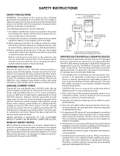
... observed: 1. Connect one half the AC line voltage in the power line between the receiver and the AC line before applying power to any television to the customer, the service technician must measure between a known good earth ground (water pipe, conduit, etc.) and all exposed metal parts of the cabinet (antennas, handle bracket, metal cabinet, screw heads, metal overlays, control shafts...
... observed: 1. Connect one half the AC line voltage in the power line between the receiver and the AC line before applying power to any television to the customer, the service technician must measure between a known good earth ground (water pipe, conduit, etc.) and all exposed metal parts of the cabinet (antennas, handle bracket, metal cabinet, screw heads, metal overlays, control shafts...
Service Manual
Page 3
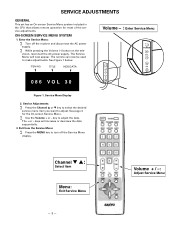
... the Service Menu: ∑ Turn off the Service Menu display. keys will now appear. Volume + / -: Adjust Service Menu Service Menu Display 2. Service Adjustments: ∑ Press the Channel L or M key to select the desired service menu item you want to adjust the data. Channel M L: Select Item Menu: Exit Service Menu - 3 - ITEM NO. The remote can now be used to turn off the receiver and disconnect the AC power supply. ∑ While pressing the Volume (-) button on the tele- ON-SCREEN SERVICE MENU SYSTEM 1. SERVICE ADJUSTMENTS GENERAL This set...
... the Service Menu: ∑ Turn off the Service Menu display. keys will now appear. Volume + / -: Adjust Service Menu Service Menu Display 2. Service Adjustments: ∑ Press the Channel L or M key to select the desired service menu item you want to adjust the data. Channel M L: Select Item Menu: Exit Service Menu - 3 - ITEM NO. The remote can now be used to turn off the receiver and disconnect the AC power supply. ∑ While pressing the Volume (-) button on the tele- ON-SCREEN SERVICE MENU SYSTEM 1. SERVICE ADJUSTMENTS GENERAL This set...
Service Manual
Page 4
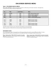
... Data 2 (NO. 088 OP2) should be set according to confirm they are the same as below. If this program code is fixed. ON-SCREEN SERVICE MENU Table 1. No. Title 1A0 MUTE 086 VOL 087 OP1 088 OP2 Initial Data A0h 30h 40h 08h Note Audio mute at Power ON Volume setup inspection Option 1 Data (HDMI) Option 2 Data (Display Panel) 101 1R00 102 1R01 ↓ ↓...
... Data 2 (NO. 088 OP2) should be set according to confirm they are the same as below. If this program code is fixed. ON-SCREEN SERVICE MENU Table 1. No. Title 1A0 MUTE 086 VOL 087 OP1 088 OP2 Initial Data A0h 30h 40h 08h Note Audio mute at Power ON Volume setup inspection Option 1 Data (HDMI) Option 2 Data (Display Panel) 101 1R00 102 1R01 ↓ ↓...
Service Manual
Page 6
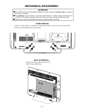
... must be redressed to their previous positions after servicing. Remove 4 screws (6X16) and remove stand. B:3X8, 3pc;) -6- Using the correct screw is required to other radio and television receivers. I This LCD TV uses several different kinds of screws. BACK LID REMOVAL Remove 5 screws to protect the screen and finish. The gaskets must be returned to previous positions after servicing. STAND REMOVAL Position TV face down on a padded or cushioned surface to...
... must be redressed to their previous positions after servicing. Remove 4 screws (6X16) and remove stand. B:3X8, 3pc;) -6- Using the correct screw is required to other radio and television receivers. I This LCD TV uses several different kinds of screws. BACK LID REMOVAL Remove 5 screws to protect the screen and finish. The gaskets must be returned to previous positions after servicing. STAND REMOVAL Position TV face down on a padded or cushioned surface to...


