Owners Manual
Page 4
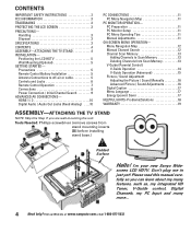
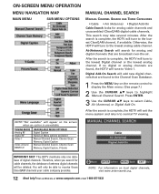
...) Saver 17 HELPFUL HINTS-Problems/Solutions 18 WARRANTY 19 ASSEMBLY-ATTACHING THE TV STAND NOTE: Skip this manual carefully so you are wall-mounting the...Remote Control Battery Installation 5 Antenna Connections to Scan Memory 13 Deleting Channels from stand mounting inserts [D] before installing stand base.) Padded Surface Hello! Visit our Web site at www.sanyoctv.com or Call 1-800-877-5032 CONTENTS IMPORTANT SAFETY INSTRUCTIONS 2 FCC INFORMATION 3 TRADEMARKS 3 PROTECTING THE LCD...your new Sanyo Wide- Handling 3 Disposal 3 SPECIFICATIONS 3 CONTENTS 4 ASSEMBLY-ATTACHING THE...
...) Saver 17 HELPFUL HINTS-Problems/Solutions 18 WARRANTY 19 ASSEMBLY-ATTACHING THE TV STAND NOTE: Skip this manual carefully so you are wall-mounting the...Remote Control Battery Installation 5 Antenna Connections to Scan Memory 13 Deleting Channels from stand mounting inserts [D] before installing stand base.) Padded Surface Hello! Visit our Web site at www.sanyoctv.com or Call 1-800-877-5032 CONTENTS IMPORTANT SAFETY INSTRUCTIONS 2 FCC INFORMATION 3 TRADEMARKS 3 PROTECTING THE LCD...your new Sanyo Wide- Handling 3 Disposal 3 SPECIFICATIONS 3 CONTENTS 4 ASSEMBLY-ATTACHING THE...
Owners Manual
Page 5
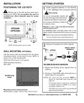
... recycle used up rechargeable batteries. OR b. Do not expose the Remote or batteries to your battery charger's instructions (battery charger not included... (OPTIONAL) 2 Antenna Connection for off -air signals from a direct Cable TV connection. NOTES: You must use a firm-flat surface when positioning your HDTV... Web site at www.sanyoctv.com or Call 1-800-877-5032 5 DP26648 (DP32648) GETTING STARTED 1 Install supplied batteries in a confined area. ...IN Use the screws that are in inches. INSTALLATION POSITIONING THE LCD HDTV Always use the on-screen MENU to Search for ClearQAM...
... recycle used up rechargeable batteries. OR b. Do not expose the Remote or batteries to your battery charger's instructions (battery charger not included... (OPTIONAL) 2 Antenna Connection for off -air signals from a direct Cable TV connection. NOTES: You must use a firm-flat surface when positioning your HDTV... Web site at www.sanyoctv.com or Call 1-800-877-5032 5 DP26648 (DP32648) GETTING STARTED 1 Install supplied batteries in a confined area. ...IN Use the screws that are in inches. INSTALLATION POSITIONING THE LCD HDTV Always use the on-screen MENU to Search for ClearQAM...
Owners Manual
Page 7
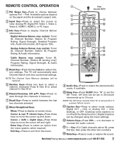
...these keys to restore factory settings. Digital Antenna Banner may contain: Tuner ID, Channel Number, Station ID, Program Rating, & Audio Information. The TV will be replaced. Number Keys-Press two keys to select mode options: Digital CC1 ~ CC6, or Analog CC1 ~ CC4, QuikCap... Banner information. NOTE:The Channel Scan Memory database will automatically start Channel Search and clear customized settings. Available options depend on -screen menu. REMOTE CONTROL OPERATION Œ PIX Shape Key-Press to select an option from the menu. « Œ Point towards HDTV &#...
...these keys to restore factory settings. Digital Antenna Banner may contain: Tuner ID, Channel Number, Station ID, Program Rating, & Audio Information. The TV will be replaced. Number Keys-Press two keys to select mode options: Digital CC1 ~ CC6, or Analog CC1 ~ CC4, QuikCap... Banner information. NOTE:The Channel Scan Memory database will automatically start Channel Search and clear customized settings. Available options depend on -screen menu. REMOTE CONTROL OPERATION Œ PIX Shape Key-Press to select an option from the menu. « Œ Point towards HDTV &#...
Owners Manual
Page 12
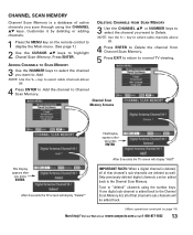
... Air (Antenna), or Digital Add-On. NOTE:"Not available" will only be deleted. After the search is complete, the HDTV will tune to normal TV viewing. After the search is unavailable. Visit our Web site at www.sanyoctv.com or Call 1-800-877-5032 If no digital or analog channels...channel, if available. Otherwise, the HDTV will add new digital channels that are found to the Channel Scan Database. 1 Press the MENU key on the remote control to display the Main menu. (See page 7.) 2 Use the CURSOR LM keys to the lowest analog cable channel. Digital Add-On Search will...
... Air (Antenna), or Digital Add-On. NOTE:"Not available" will only be deleted. After the search is complete, the HDTV will tune to normal TV viewing. After the search is unavailable. Visit our Web site at www.sanyoctv.com or Call 1-800-877-5032 If no digital or analog channels...channel, if available. Otherwise, the HDTV will add new digital channels that are found to the Channel Scan Database. 1 Press the MENU key on the remote control to display the Main menu. (See page 7.) 2 Use the CURSOR LM keys to the lowest analog cable channel. Digital Add-On Search will...
Owners Manual
Page 13
...select the channel you want to highlight Chanel Scan Memory. Only previously deleted digital channels can be added back. (Menu operations continued on the remote control to display the Main menu. (See page 7.) 2 Use the CURSOR LM keys to Delete. Channel Scan Memory Screens This Display ...Press ENTER. IMPORTANT FACTS: When a digital channel is deleted, all of that channel's sub-channels are deleted as well. After 3 seconds the TV screen will display "Delete?" This Display appears after you press ENTER. key to select cable channels above 99. 4 Press ENTER to Delete the channel...
...select the channel you want to highlight Chanel Scan Memory. Only previously deleted digital channels can be added back. (Menu operations continued on the remote control to display the Main menu. (See page 7.) 2 Use the CURSOR LM keys to Delete. Channel Scan Memory Screens This Display ...Press ENTER. IMPORTANT FACTS: When a digital channel is deleted, all of that channel's sub-channels are deleted as well. After 3 seconds the TV screen will display "Delete?" This Display appears after you press ENTER. key to select cable channels above 99. 4 Press ENTER to Delete the channel...

Owners Manual
Page 18
...signal booster. G Set V-Guide to restart channel search. (All customized settings will not operate TV Cabinet makes popping sound. G Check if TV is a normal condition during warm-up and cool down of TV. 13 5, 7 18 Need help? G This is plugged in color. G Select another ...Select Channel Scan Memory to select captioning mode. G Turn antenna, install signal booster. 5, 7 7 13 - 15 No Cable channels above number 13 Remote Control will be ON. G Press INPUT. No picture, sound (Digital Picture) G Check antenna/external connections G May be station trouble. G Color or...
...signal booster. G Set V-Guide to restart channel search. (All customized settings will not operate TV Cabinet makes popping sound. G Check if TV is a normal condition during warm-up and cool down of TV. 13 5, 7 18 Need help? G This is plugged in color. G Select another ...Select Channel Scan Memory to select captioning mode. G Turn antenna, install signal booster. 5, 7 7 13 - 15 No Cable channels above number 13 Remote Control will be ON. G Press INPUT. No picture, sound (Digital Picture) G Check antenna/external connections G May be station trouble. G Color or...
Owners Manual
Page 19
... the date of original retail purchase Sanyo Manufacturing Corporation (SMC) warrants this TV to be free from state to be exchanged for evidence of unit) Purchase Price Where Purchased US1-F Sanyo Manufacturing Corp. 3333 Sanyo Road, Forrest City, AR 72335 26-N6CE / 32-N6DE GXBJ [This... manual printed with the receipt and the included accessories, such as the remote control...
... the date of original retail purchase Sanyo Manufacturing Corporation (SMC) warrants this TV to be free from state to be exchanged for evidence of unit) Purchase Price Where Purchased US1-F Sanyo Manufacturing Corp. 3333 Sanyo Road, Forrest City, AR 72335 26-N6CE / 32-N6DE GXBJ [This... manual printed with the receipt and the included accessories, such as the remote control...
Service Manual
Page 1
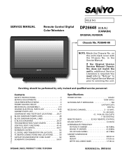
....25MHz COLOR SUB CARRIEr 42.17MHz CABINET DIMENSIONS WIDTH 665.5mm HEIGHT 515.6mm DEPTH INCLUDING BASE 177.8mm © Sanyo Manufacturing Corporation 2008 DP26648, N6CE, PRODUCT CODE 113013904 REFERENCE No. SERVICE MANUAL Remote Control Digital Color Television FILE NO. in the Service Manual. SM780150 does not match the unit's, additional Service Literature...
....25MHz COLOR SUB CARRIEr 42.17MHz CABINET DIMENSIONS WIDTH 665.5mm HEIGHT 515.6mm DEPTH INCLUDING BASE 177.8mm © Sanyo Manufacturing Corporation 2008 DP26648, N6CE, PRODUCT CODE 113013904 REFERENCE No. SERVICE MANUAL Remote Control Digital Color Television FILE NO. in the Service Manual. SM780150 does not match the unit's, additional Service Literature...
Service Manual
Page 3
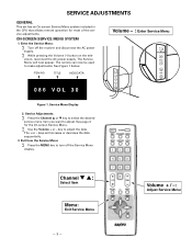
... the MENU key to adjust the data. vision, reconnect the AC power supply. The Service Menu will increase or decrease the data sequentially. 3. The remote can now be used to adjust. Service Menu Display 2. Service Adjustments: ∑ Press the Channel L or M key to select the desired service ...3 - ON-SCREEN SERVICE MENU SYSTEM 1. SERVICE ADJUSTMENTS GENERAL This set has an On-screen Service Menu system included in the CPU that allows remote operation for the On-screen Service Menu. ∑ Use the Volume + or - TITLE HEX DATA Volume - : Enter Service Menu 086 VOL 30 ...
... the MENU key to adjust the data. vision, reconnect the AC power supply. The Service Menu will increase or decrease the data sequentially. 3. The remote can now be used to adjust. Service Menu Display 2. Service Adjustments: ∑ Press the Channel L or M key to select the desired service ...3 - ON-SCREEN SERVICE MENU SYSTEM 1. SERVICE ADJUSTMENTS GENERAL This set has an On-screen Service Menu system included in the CPU that allows remote operation for the On-screen Service Menu. ∑ Use the Volume + or - TITLE HEX DATA Volume - : Enter Service Menu 086 VOL 30 ...
Service Manual
Page 43
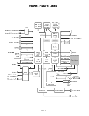
VBL +12/24V Remote IR Key Switch Power LED Audio Cnt. TV Speakers Line Out - 43 - Audio Amp. SIGNAL FLOW CHARTS SW Video 2 (Component) Video 3 (Component) PC (D-Sub) HDMI1 (or DVI) I²C RF-IN HDMI2 I²C Digital/ ... Back Light level Video data & Clk (LVDS) Panel Unit Video2 Video3 Audio (or DVI Audio) PC Audio (L/R) A A I²S I²C L/R UART A A Audio A-out Selector Audio ADC A TV CPU EEPROM +12/5/3.3V Vcc cont.
VBL +12/24V Remote IR Key Switch Power LED Audio Cnt. TV Speakers Line Out - 43 - Audio Amp. SIGNAL FLOW CHARTS SW Video 2 (Component) Video 3 (Component) PC (D-Sub) HDMI1 (or DVI) I²C RF-IN HDMI2 I²C Digital/ ... Back Light level Video data & Clk (LVDS) Panel Unit Video2 Video3 Audio (or DVI Audio) PC Audio (L/R) A A I²S I²C L/R UART A A Audio A-out Selector Audio ADC A TV CPU EEPROM +12/5/3.3V Vcc cont.

Service Manual
Page 44
TV Speakers Line Out - 44 - VBL +12/24V Remote IR Key Switch Power LED Audio Cnt. Audio Amp. SW SPI Flash (32 Mbit) DDR2 256Mbit (400MHz) DDR2 256Mbit (400MHz) Video 2 (Component) Video 3 (Component) PC (D-... Back Light level Video data & Clk (LVDS) Panel Unit Video2 Video3 Audio (or DVI Audio) PC Audio (L/R) A A I²S I²C L/R UART A Audio A-out Audio A Selector ADC TV CPU A EEPROM +12/5/3.3V Vcc cont.
TV Speakers Line Out - 44 - VBL +12/24V Remote IR Key Switch Power LED Audio Cnt. Audio Amp. SW SPI Flash (32 Mbit) DDR2 256Mbit (400MHz) DDR2 256Mbit (400MHz) Video 2 (Component) Video 3 (Component) PC (D-... Back Light level Video data & Clk (LVDS) Panel Unit Video2 Video3 Audio (or DVI Audio) PC Audio (L/R) A A I²S I²C L/R UART A Audio A-out Audio A Selector ADC TV CPU A EEPROM +12/5/3.3V Vcc cont.
Service Manual
Page 45
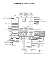
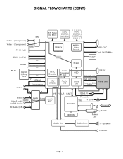
VBL +12/24V Remote IR Key Switch Power LED Audio Cnt. Audio Amp. TV Speakers Line Out - 45 - SIGNAL FLOW CHARTS (CONT.) SW SPI Flash (32 Mbit) DDR2 256Mbit (400MHz) DDR2 256Mbit (400MHz) Video 2 (Component) Video 3 (Component) PC (D-Sub) ... Light level Video data & Clk (LVDS) Panel Unit A Audio Video2 A Video3 Audio A (or DVI Audio) PC Audio (L/R) A A Audio A-out Selector I²S I²C L/R Audio ADC UART TV CPU EEPROM +12/5/3.3V Vcc cont.
VBL +12/24V Remote IR Key Switch Power LED Audio Cnt. Audio Amp. TV Speakers Line Out - 45 - SIGNAL FLOW CHARTS (CONT.) SW SPI Flash (32 Mbit) DDR2 256Mbit (400MHz) DDR2 256Mbit (400MHz) Video 2 (Component) Video 3 (Component) PC (D-Sub) ... Light level Video data & Clk (LVDS) Panel Unit A Audio Video2 A Video3 Audio A (or DVI Audio) PC Audio (L/R) A A Audio A-out Selector I²S I²C L/R Audio ADC UART TV CPU EEPROM +12/5/3.3V Vcc cont.
Service Manual
Page 46
Audio Amp. TV Speakers Line Out - 46 - VBL +12/24V Remote IR Key Switch Power LED Audio Cnt. Video 2 (Component) Video 3 (Component) Video SW PC (D-Sub) SPI Flash (32 Mbit) DDR2 256Mbit (400MHz) DDR2 256Mbit (400MHz) ... Light level Video data & Clk (LVDS) Panel Unit A Audio Video2 A Video3 Audio A (or DVI Audio) PC Audio (L/R) A A Audio A-out Selector I²S I²C L/R Audio ADC UART TV CPU EEPROM +12/5/3.3V Vcc cont.
Audio Amp. TV Speakers Line Out - 46 - VBL +12/24V Remote IR Key Switch Power LED Audio Cnt. Video 2 (Component) Video 3 (Component) Video SW PC (D-Sub) SPI Flash (32 Mbit) DDR2 256Mbit (400MHz) DDR2 256Mbit (400MHz) ... Light level Video data & Clk (LVDS) Panel Unit A Audio Video2 A Video3 Audio A (or DVI Audio) PC Audio (L/R) A A Audio A-out Selector I²S I²C L/R Audio ADC UART TV CPU EEPROM +12/5/3.3V Vcc cont.
Service Manual
Page 47
VBL +12/24V Remote IR Key Switch Power LED Audio Cnt. TV Speakers Line Out - 47 - Audio Amp. SIGNAL FLOW CHARTS (CONT.) Video 2 (Component) Video 3 (Component) PC (D-Sub) SW Video SPI Flash (32 Mbit) DDR2 256Mbit (400MHz) ... Light level Video data & Clk (LVDS) Panel Unit A Video2 A Audio Video3 Audio A (or DVI Audio) PC Audio (L/R) A A Audio A-out Selector I²S I²C L/R Audio ADC UART TV CPU EEPROM +12/5/3.3V Vcc cont.
VBL +12/24V Remote IR Key Switch Power LED Audio Cnt. TV Speakers Line Out - 47 - Audio Amp. SIGNAL FLOW CHARTS (CONT.) Video 2 (Component) Video 3 (Component) PC (D-Sub) SW Video SPI Flash (32 Mbit) DDR2 256Mbit (400MHz) ... Light level Video data & Clk (LVDS) Panel Unit A Video2 A Audio Video3 Audio A (or DVI Audio) PC Audio (L/R) A A Audio A-out Selector I²S I²C L/R Audio ADC UART TV CPU EEPROM +12/5/3.3V Vcc cont.
Service Manual
Page 48
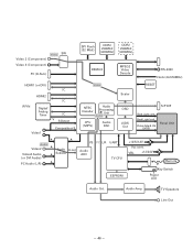
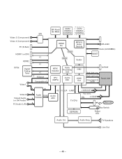
TV Speakers Line Out - 48 - SW Video 2 (Component) Video 3 (Component) PC (D-Sub) HDMI1 (or DVI) I²C RF-IN HDMI2 I²C Digital/ Analog Tuner I²C V S-Detect Video1 ... Back Light level Video data & Clk (LVDS) Panel Unit Video2 Video3 Audio (or DVI Audio) PC Audio (L/R) A A I²S I²C L/R UART A Audio A-out Audio A Selector ADC TV CPU A EEPROM +12/5/3.3V Vcc cont. Audio Amp. VBL +12/24V Remote IR Key Switch Power LED Audio Cnt.
TV Speakers Line Out - 48 - SW Video 2 (Component) Video 3 (Component) PC (D-Sub) HDMI1 (or DVI) I²C RF-IN HDMI2 I²C Digital/ Analog Tuner I²C V S-Detect Video1 ... Back Light level Video data & Clk (LVDS) Panel Unit Video2 Video3 Audio (or DVI Audio) PC Audio (L/R) A A I²S I²C L/R UART A Audio A-out Audio A Selector ADC TV CPU A EEPROM +12/5/3.3V Vcc cont. Audio Amp. VBL +12/24V Remote IR Key Switch Power LED Audio Cnt.

Service Manual
Page 49
VBL +12/24V Remote IR Key Switch Power LED Audio Cnt. TV Speakers Line Out - 49 - SIGNAL FLOW CHARTS (CONT.) SW Video 2 (Component) Video 3 (Component) PC (D-Sub) HDMI1 (or DVI) I²C RF-IN HDMI2 I²C Digital/ Analog ... Back Light level Video data & Clk (LVDS) Panel Unit Video2 Video3 Audio (or DVI Audio) PC Audio (L/R) A A I²S I²C L/R UART A Audio A-out Audio A Selector ADC TV CPU A EEPROM +12/5/3.3V Vcc cont. Audio Amp.
VBL +12/24V Remote IR Key Switch Power LED Audio Cnt. TV Speakers Line Out - 49 - SIGNAL FLOW CHARTS (CONT.) SW Video 2 (Component) Video 3 (Component) PC (D-Sub) HDMI1 (or DVI) I²C RF-IN HDMI2 I²C Digital/ Analog ... Back Light level Video data & Clk (LVDS) Panel Unit Video2 Video3 Audio (or DVI Audio) PC Audio (L/R) A A I²S I²C L/R UART A Audio A-out Audio A Selector ADC TV CPU A EEPROM +12/5/3.3V Vcc cont. Audio Amp.

Service Manual
Page 50
VBL +12/24V Remote IR Key Switch Power LED Audio Cnt. TV Speakers Line Out - 50 - Audio Amp. SW Video 2 (Component) Video 3 (Component) PC (D-Sub) HDMI1 (or DVI) I²C RF-IN HDMI2 I²C Digital/ Analog Tuner I²C V S-... Back Light level Video data & Clk (LVDS) Panel Unit Video2 Video3 Audio (or DVI Audio) PC Audio (L/R) A A I²S I²C L/R UART A Audio A-out Audio A Selector ADC TV CPU A EEPROM +12/5/3.3V Vcc cont.
VBL +12/24V Remote IR Key Switch Power LED Audio Cnt. TV Speakers Line Out - 50 - Audio Amp. SW Video 2 (Component) Video 3 (Component) PC (D-Sub) HDMI1 (or DVI) I²C RF-IN HDMI2 I²C Digital/ Analog Tuner I²C V S-... Back Light level Video data & Clk (LVDS) Panel Unit Video2 Video3 Audio (or DVI Audio) PC Audio (L/R) A A I²S I²C L/R UART A Audio A-out Audio A Selector ADC TV CPU A EEPROM +12/5/3.3V Vcc cont.

Service Manual
Page 51
VBL +12/24V Remote IR Key Switch Power LED Audio Cnt. TV Speakers Line Out - 51 - Audio Amp. SIGNAL FLOW CHARTS (CONT.) SW Video 2 (Component) Video 3 (Component) PC (D-Sub) HDMI1 (or DVI) I²C RF-IN HDMI2 I²C ... Back Light level Video data & Clk (LVDS) Panel Unit Video2 Video3 Audio (or DVI Audio) PC Audio (L/R) A A I²S I²C L/R UART A Audio A-out Audio A Selector ADC A TV CPU EEPROM +12/5/3.3V Vcc cont.
VBL +12/24V Remote IR Key Switch Power LED Audio Cnt. TV Speakers Line Out - 51 - Audio Amp. SIGNAL FLOW CHARTS (CONT.) SW Video 2 (Component) Video 3 (Component) PC (D-Sub) HDMI1 (or DVI) I²C RF-IN HDMI2 I²C ... Back Light level Video data & Clk (LVDS) Panel Unit Video2 Video3 Audio (or DVI Audio) PC Audio (L/R) A A I²S I²C L/R UART A Audio A-out Audio A Selector ADC A TV CPU EEPROM +12/5/3.3V Vcc cont.


