Owners Manual
Page 2
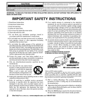
... circuits, or where it can fall into the apparatus, the apparatus has been exposed to dripping or splashing and no objects filled with the cart, stand, tripod, bracket, or table specified by the manufacturer. 12. "Apparatus shall not be exposed to rain or moisture, does not operate normally, or has been...
... circuits, or where it can fall into the apparatus, the apparatus has been exposed to dripping or splashing and no objects filled with the cart, stand, tripod, bracket, or table specified by the manufacturer. 12. "Apparatus shall not be exposed to rain or moisture, does not operate normally, or has been...
Owners Manual
Page 4
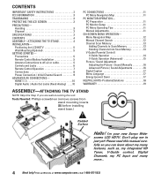
...Audio / Audio Out Jacks (Fixed Analog) . . . .10 PC CONNECTIONS 11 PC Menu Navigation Map 11 PC MONITOR OPERATION- I'm your new Sanyo Wide- screen LCD HDTV. PC Preparation 11 PC Monitor Setup 11 PC Menu Operating Tips 11 Manual Adjustments 11 ON-SCREEN MENU OPERATION- Tools Needed: Phillips screwdriver...Adjustments 16 Digital Caption 17 Menu Language 17 Energy (power) Saver 17 HELPFUL HINTS-Problems/Solutions 18 WARRANTY 19 ASSEMBLY-ATTACHING THE TV STAND NOTE: Skip this manual carefully so you are wall-mounting the unit. Visit our Web site at www.sanyoctv.com or Call...
...Audio / Audio Out Jacks (Fixed Analog) . . . .10 PC CONNECTIONS 11 PC Menu Navigation Map 11 PC MONITOR OPERATION- I'm your new Sanyo Wide- screen LCD HDTV. PC Preparation 11 PC Monitor Setup 11 PC Menu Operating Tips 11 Manual Adjustments 11 ON-SCREEN MENU OPERATION- Tools Needed: Phillips screwdriver...Adjustments 16 Digital Caption 17 Menu Language 17 Energy (power) Saver 17 HELPFUL HINTS-Problems/Solutions 18 WARRANTY 19 ASSEMBLY-ATTACHING THE TV STAND NOTE: Skip this manual carefully so you are wall-mounting the unit. Visit our Web site at www.sanyoctv.com or Call...
Service Manual
Page 6
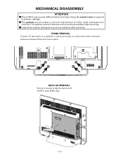
...gaskets must be returned to their previous positions after servicing. STAND REMOVAL Position TV face down on a padded or cushioned surface to take the back Lid off. (A:3X14, 2pcs; Remove 4 screws (6X16) and remove stand. B:3X8, 3pc;) -6- MECHANICAL DISASSEMBLY ATTENTION I The ...gaskets are provided to prevent interference to other radio and television receivers. BACK LID REMOVAL Remove 5 screws to protect the screen and finish. I Lead wires must be redressed to prevent damage. I This LCD TV uses ...
...gaskets must be returned to their previous positions after servicing. STAND REMOVAL Position TV face down on a padded or cushioned surface to take the back Lid off. (A:3X14, 2pcs; Remove 4 screws (6X16) and remove stand. B:3X8, 3pc;) -6- MECHANICAL DISASSEMBLY ATTENTION I The ...gaskets are provided to prevent interference to other radio and television receivers. BACK LID REMOVAL Remove 5 screws to protect the screen and finish. I Lead wires must be redressed to prevent damage. I This LCD TV uses ...
Service Manual
Page 7
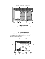
POWER AND MAIN BOARD REMOVAL 1: Main Board Removal Remove 5 screws (3X14) to take the main board off. 2: Power Unit Removal Remove 6 screws (3X14) to take the power unit off . 3. Once you have taken off the Lid back, stand base, power unit and main board remove 9 screws (C:3X14) and 4 screws (D:4X8) to take the back cabinet off LCD panel removal Removal 1. Lift the LCD panel from LCD panel, speakers, and control board. 2. Disconnect the lead wires from the front cabinet. -7-
POWER AND MAIN BOARD REMOVAL 1: Main Board Removal Remove 5 screws (3X14) to take the main board off. 2: Power Unit Removal Remove 6 screws (3X14) to take the power unit off . 3. Once you have taken off the Lid back, stand base, power unit and main board remove 9 screws (C:3X14) and 4 screws (D:4X8) to take the back cabinet off LCD panel removal Removal 1. Lift the LCD panel from LCD panel, speakers, and control board. 2. Disconnect the lead wires from the front cabinet. -7-


