Owner's Manual
Page 3
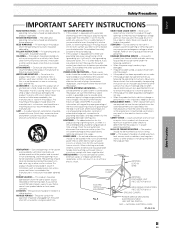
... type plug, a plug having one way. When installing an outside antenna system, extreme care should be taken to keep from the wall outlet and refer servicing to lightning and power-line surges. REPLACEMENT PARTS - NATIONAL ELECTRICAL CODE D1-4-2-2_En Safety Precautions iii EN RETAIN INSTRUCTIONS - Do not use this can result in wire to an antenna discharge unit, size of grounding conductors, location of antenna-discharge unit, connection...
... type plug, a plug having one way. When installing an outside antenna system, extreme care should be taken to keep from the wall outlet and refer servicing to lightning and power-line surges. REPLACEMENT PARTS - NATIONAL ELECTRICAL CODE D1-4-2-2_En Safety Precautions iii EN RETAIN INSTRUCTIONS - Do not use this can result in wire to an antenna discharge unit, size of grounding conductors, location of antenna-discharge unit, connection...

Owner's Manual
Page 5
...16 About DTV Set Top Box Connection 17 Audio connections 18 Connecting Control Cords 19 Power Cord Connection 20 How to Route Cables 21 System Settings 22 Setting the Onscreen Display Language 22 Settings After Connections (INPUT1, 2, 5 23 Setting SR+MODE Mode 27 Operation 29 Selecting Input Source 29 Adjusting Sound Volume 30 Muting the Sound 30 Confirming Current Status 30 Changing Screen Size 30 Multiscreen Display 32 Setting AV SELECTION 33 Picture and Screen Adjustment ......... 35 Picture Adjustment (1 35 Picture Adjustment (2 36 Picture Adjustment (3 37 Returning to...
...16 About DTV Set Top Box Connection 17 Audio connections 18 Connecting Control Cords 19 Power Cord Connection 20 How to Route Cables 21 System Settings 22 Setting the Onscreen Display Language 22 Settings After Connections (INPUT1, 2, 5 23 Setting SR+MODE Mode 27 Operation 29 Selecting Input Source 29 Adjusting Sound Volume 30 Muting the Sound 30 Confirming Current Status 30 Changing Screen Size 30 Multiscreen Display 32 Setting AV SELECTION 33 Picture and Screen Adjustment ......... 35 Picture Adjustment (1 35 Picture Adjustment (2 36 Picture Adjustment (3 37 Returning to...
Owner's Manual
Page 6
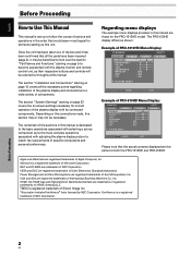
... connected components. Before Proceeding 2 EN VESA and DDC are trademarks of NEC Corporation. FontAvenue is a registered trademark of the plasma display with the plasma monitor and remote control unit, as shown: Example of PRO-1010HD Menu Display: S TA N D A R D PICTURE SCREEN SETUP CONTRAST BRIGHTNESS COLOR TINT SHARPNESS MPEG NR DNR CTI :0 :0 :0 :0 :0 : MID : MID : ON INPUT1 OPTION PICTURE RESET SET ENTER MENU EXIT Example of HDMI Licensing LLC. Depending on the connections made, this manual...
... connected components. Before Proceeding 2 EN VESA and DDC are trademarks of NEC Corporation. FontAvenue is a registered trademark of the plasma display with the plasma monitor and remote control unit, as shown: Example of PRO-1010HD Menu Display: S TA N D A R D PICTURE SCREEN SETUP CONTRAST BRIGHTNESS COLOR TINT SHARPNESS MPEG NR DNR CTI :0 :0 :0 :0 :0 : MID : MID : ON INPUT1 OPTION PICTURE RESET SET ENTER MENU EXIT Example of HDMI Licensing LLC. Depending on the connections made, this manual...
Owner's Manual
Page 7
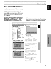
... picture adjustment setting values for the section "PICTURE adjustment". Picture and Screen Adjustment Before Proceeding MENU 5/∞ 2/3 SET MENU 2/3 SET 5/∞ AV SELECTION Display operating panel Remote control unit 1 Press the AV SELECTION button to select the desired mode (Refer to page 33). 2 Press the MENU button to select the item, then press the SET button. S TA N D A R D PICTURE SCREEN SETUP CONTRAST BRIGHTNESS COLOR TINT SHARPNESS MPEG NR DNR CTI :0 :0 :0 :0 :0 : MID : MID : ON INPUT1 OPTION PICTURE RESET SET ENTER MENU EXIT 3 Use...
... picture adjustment setting values for the section "PICTURE adjustment". Picture and Screen Adjustment Before Proceeding MENU 5/∞ 2/3 SET MENU 2/3 SET 5/∞ AV SELECTION Display operating panel Remote control unit 1 Press the AV SELECTION button to select the desired mode (Refer to page 33). 2 Press the MENU button to select the item, then press the SET button. S TA N D A R D PICTURE SCREEN SETUP CONTRAST BRIGHTNESS COLOR TINT SHARPNESS MPEG NR DNR CTI :0 :0 :0 :0 :0 : MID : MID : ON INPUT1 OPTION PICTURE RESET SET ENTER MENU EXIT 3 Use...
Owner's Manual
Page 12
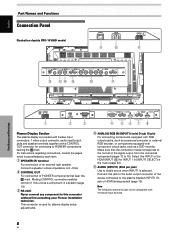
...For connection of the signal output from the connected component (pages 12 to 15). English Part Names and Functions Connection Panel Illustration depicts PRO-1010HD model. S-VIDEO INPUT3 VIDEO INPUT4 INPUT 3/4 AUDIO ANALOG RGB INPUT5 AUDIO = IN OUT R L G(ON SYNC) B R HD (H/V SYNC) VD ~! @ # R L $ Part Names and Functions R SPEAKER 8+Ω ~16Ω- 1 OUT CONTROL 2 RS-232C 3 ANALOG RGB IN D-Sub IINNPPUUTT11 AUDIO R L HDMI AUDIO INPUT2 R L HDMI 4 567 8 Plasma Display Section The plasma display is selected. Making CONTROL connection enables control of...
...For connection of the signal output from the connected component (pages 12 to 15). English Part Names and Functions Connection Panel Illustration depicts PRO-1010HD model. S-VIDEO INPUT3 VIDEO INPUT4 INPUT 3/4 AUDIO ANALOG RGB INPUT5 AUDIO = IN OUT R L G(ON SYNC) B R HD (H/V SYNC) VD ~! @ # R L $ Part Names and Functions R SPEAKER 8+Ω ~16Ω- 1 OUT CONTROL 2 RS-232C 3 ANALOG RGB IN D-Sub IINNPPUUTT11 AUDIO R L HDMI AUDIO INPUT2 R L HDMI 4 567 8 Plasma Display Section The plasma display is selected. Making CONTROL connection enables control of...

Owner's Manual
Page 13
... video output jack such as a digital set top box, DVD player, etc. Before attempting to connect one end of components connected to a standard AC power source. - SPEAKER (L) terminal For connection of components that the connection made corresponds to obtain sound when INPUT3 or INPUT4 is selected. connect one of the plasma display on and off. 0 AC IN A power cable is off or in the menu (page 23). 7 AUDIO (INPUT2) (RCA Pin jacks) Use...
... video output jack such as a digital set top box, DVD player, etc. Before attempting to connect one end of components connected to a standard AC power source. - SPEAKER (L) terminal For connection of components that the connection made corresponds to obtain sound when INPUT3 or INPUT4 is selected. connect one of the plasma display on and off. 0 AC IN A power cable is off or in the menu (page 23). 7 AUDIO (INPUT2) (RCA Pin jacks) Use...

Owner's Manual
Page 16
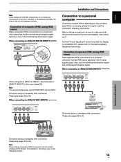
... source Make G ON SYNC connections for a component with component video jacks. English Installation and Connections Connection to AV components Connection to ANALOG RGB (INPUT5) ANALOG RGB INPUT5 G(ON SYNC) B R HD (H/V SYNC) VD When using D-sub INPUT for INPUT1, select [D-sub] in [INPUT1 SELECT] in the menu (page 23). Connection of the green signal. As a result, some image disruption may be generated during use commercially available BNC/pin-plug conversion adapters...
... source Make G ON SYNC connections for a component with component video jacks. English Installation and Connections Connection to AV components Connection to ANALOG RGB (INPUT5) ANALOG RGB INPUT5 G(ON SYNC) B R HD (H/V SYNC) VD When using D-sub INPUT for INPUT1, select [D-sub] in [INPUT1 SELECT] in the menu (page 23). Connection of the green signal. As a result, some image disruption may be generated during use commercially available BNC/pin-plug conversion adapters...
Owner's Manual
Page 17
... use the HDMI INPUT and this INPUT. Before making connections, be sure to make any connections to , the picture may be displayed properly. 13 EN Installation and Connections On-screen setup is compatible with output that has RGB output separated into 5 output signals: green, blue, red, horizontal synchronization signal, and vertical synchronization signal. If connected to the VD or HD jacks. When connecting, please thoroughly read the computer's operating instructions. Connection of composite SYNC analog RGB source Make composite SYNC connections...
... use the HDMI INPUT and this INPUT. Before making connections, be sure to make any connections to , the picture may be displayed properly. 13 EN Installation and Connections On-screen setup is compatible with output that has RGB output separated into 5 output signals: green, blue, red, horizontal synchronization signal, and vertical synchronization signal. If connected to the VD or HD jacks. When connecting, please thoroughly read the computer's operating instructions. Connection of composite SYNC analog RGB source Make composite SYNC connections...

Owner's Manual
Page 19
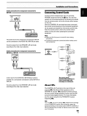
... with a digital video output (digital set top box, DVD player, etc.) compatible with HDCP (High-bandwidth Digital Content Protection). Note You cannot simultaneously use the HDMI INPUT and this INPUT. Notes ÷ Use a HDMI (High Definition Multimedia Interface) cable for connection. ÷ When connecting a component with DVI connector, use D-sub INPUT and this INPUT. On-screen setup is necessary after connection. HDMI, the HDMI logo and High-Definition Multimedia Interface are equipped with both G ON SYNC and composite SYNC outputs. Before...
... with a digital video output (digital set top box, DVD player, etc.) compatible with HDCP (High-bandwidth Digital Content Protection). Note You cannot simultaneously use the HDMI INPUT and this INPUT. Notes ÷ Use a HDMI (High Definition Multimedia Interface) cable for connection. ÷ When connecting a component with DVI connector, use D-sub INPUT and this INPUT. On-screen setup is necessary after connection. HDMI, the HDMI logo and High-Definition Multimedia Interface are equipped with both G ON SYNC and composite SYNC outputs. Before...
Owner's Manual
Page 23
... OUT CONTROL CONTROL IN SR OUT Installation and Connections CONTROL IN SR OUT Audio input to the AUDIO R/L (INPUT3/4) pin jacks is output from the remote control units. The control cables (commercially available) are mono sound cables with a PIONEER AV receiver. Sound is possible for the PIONEER AV receiver supporting SR+. SR+ presents functions such as the input switch linkage operation function and the DSP surround mode display function. When doing this, assign the appropriate setting...
... OUT CONTROL CONTROL IN SR OUT Installation and Connections CONTROL IN SR OUT Audio input to the AUDIO R/L (INPUT3/4) pin jacks is output from the remote control units. The control cables (commercially available) are mono sound cables with a PIONEER AV receiver. Sound is possible for the PIONEER AV receiver supporting SR+. SR+ presents functions such as the input switch linkage operation function and the DSP surround mode display function. When doing this, assign the appropriate setting...
Owner's Manual
Page 25
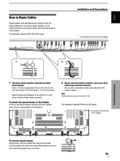
...designed to be damaged when removed. 21 EN Please attach carefully. Once components are included with the plasma display for bunching cables together. Installation and Connections * As viewed from the rear of cables. Note Cables can be placed on the ends of the display. Insert 1 into the ... depending on the rear of 1 to fix the clamp. To attach the speed clamps to the display Connect the speed clamps using the provided speed clamps. The illustration depicts PRO-1010 HD model. * As viewed from the rear of the display. 12 1 Organize cables together using the 6 holes ...
...designed to be damaged when removed. 21 EN Please attach carefully. Once components are included with the plasma display for bunching cables together. Installation and Connections * As viewed from the rear of cables. Note Cables can be placed on the ends of the display. Insert 1 into the ... depending on the rear of 1 to fix the clamp. To attach the speed clamps to the display Connect the speed clamps using the provided speed clamps. The illustration depicts PRO-1010 HD model. * As viewed from the rear of the display. 12 1 Organize cables together using the 6 holes ...

Owner's Manual
Page 26
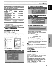
...+ MODE : ENGLISH : STANDARD : OFF : DISABLE : OFF : ON : D-SUB : OFF System Settings MENU 5/∞ STANDBY/ ON 2/3 SET MENU 2/3 SET 5/∞ Display operating panel Remote control unit 1 Set the rear panel MAIN POWER switch to select [LANGUAGE], then press the SET button. To change the setting. 4 Use the 2/3 buttons to select [OPTION]. The STANDBY indicator on the front panel will be set , regardless of the type of INPUT 1 to INPUT 5, the same display language will light green. 3 Press the MENU button to display the menu screen. S TA N D A R D PICTURE SCREEN SETUP...
...+ MODE : ENGLISH : STANDARD : OFF : DISABLE : OFF : ON : D-SUB : OFF System Settings MENU 5/∞ STANDBY/ ON 2/3 SET MENU 2/3 SET 5/∞ Display operating panel Remote control unit 1 Set the rear panel MAIN POWER switch to select [LANGUAGE], then press the SET button. To change the setting. 4 Use the 2/3 buttons to select [OPTION]. The STANDBY indicator on the front panel will be set , regardless of the type of INPUT 1 to INPUT 5, the same display language will light green. 3 Press the MENU button to display the menu screen. S TA N D A R D PICTURE SCREEN SETUP...
Owner's Manual
Page 27
... been connected to INPUT1, INPUT2 or INPUT5, on-screen setup is not supported when inputting a computer signal, or when the [SIGNAL FORMAT] function has been used to select a signal other signal frequency formats is performed automatically, so no manual setting is required (Setting [SIGNAL FORMAT] is not possible). ÷ The [COLOR DECODING] setting is necessary. S TA N D A R D INPUT1 PICTURE SCREEN SETUP OPTION LANGUAGE ENERGY SAVE POWER MANAGEMENT AUTO POWER OFF ORBITER MASK CONTROL INPUT1 SELECT SR+ MODE : ENGLISH...
... been connected to INPUT1, INPUT2 or INPUT5, on-screen setup is not supported when inputting a computer signal, or when the [SIGNAL FORMAT] function has been used to select a signal other signal frequency formats is performed automatically, so no manual setting is required (Setting [SIGNAL FORMAT] is not possible). ÷ The [COLOR DECODING] setting is necessary. S TA N D A R D INPUT1 PICTURE SCREEN SETUP OPTION LANGUAGE ENERGY SAVE POWER MANAGEMENT AUTO POWER OFF ORBITER MASK CONTROL INPUT1 SELECT SR+ MODE : ENGLISH...
Owner's Manual
Page 29
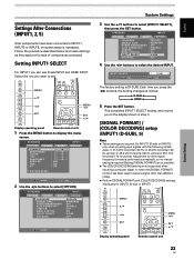
...instruction manual supplied with RGB output RGB video output of a DVD player, etc. S TA N D A R D PICTURE SCREEN SETUP PURECINEMA : OFF CLAMP POSITION : AUTO SIGNAL FORMAT : 480p COLOR DECODING : RGB HDMI INPUT BRT. ENHANCE : ON INPUT1 OPTION 4 Use the 2/3 buttons to [LOCKED]. System Settings 25 EN Please take care when making settings. Each time you to the normal display. Setting HDMI (INPUT1 (HDMI), 2) Perform setting after completing HDMI connection to select [CLAMP POSITION] then press the SET button. Connected component SETUP SIGNAL FORMAT Component video output...
...instruction manual supplied with RGB output RGB video output of a DVD player, etc. S TA N D A R D PICTURE SCREEN SETUP PURECINEMA : OFF CLAMP POSITION : AUTO SIGNAL FORMAT : 480p COLOR DECODING : RGB HDMI INPUT BRT. ENHANCE : ON INPUT1 OPTION 4 Use the 2/3 buttons to [LOCKED]. System Settings 25 EN Please take care when making settings. Each time you to the normal display. Setting HDMI (INPUT1 (HDMI), 2) Perform setting after completing HDMI connection to select [CLAMP POSITION] then press the SET button. Connected component SETUP SIGNAL FORMAT Component video output...
Owner's Manual
Page 33
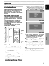
STANDBY/ ON INPUT STANDBY/ ON INPUT VOLUME [+/-] • When the menu screen is displayed, changing the signal input will cause the menu screen to turn off . • If the input computer signal is how to turn the power ON. Display operating panel Remote control unit VOLUME [+/-] 1 Set the rear panel MAIN POWER switch to adjust the sound volume. This is a result of residual electric load impressed on the circuitry, and the light will light red. 2 Press the STANDBY/ON button to put this step is not necessary...
STANDBY/ ON INPUT STANDBY/ ON INPUT VOLUME [+/-] • When the menu screen is displayed, changing the signal input will cause the menu screen to turn off . • If the input computer signal is how to turn the power ON. Display operating panel Remote control unit VOLUME [+/-] 1 Set the rear panel MAIN POWER switch to adjust the sound volume. This is a result of residual electric load impressed on the circuitry, and the light will light red. 2 Press the STANDBY/ON button to put this step is not necessary...
Owner's Manual
Page 37
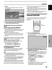
... main screen. If the DISPLAY button is pressed while in reduced size as follows: During video signal input 3 DYNAMIC 3 STANDARD USER 2 GAME 2 MOVIE 2 During PC signal input 3 STANDARD USER 2 The factory setting is DYNAMIC for video signal input and STANDARD for short periods on an everyday basis, a residual image pattern may be burned onto the screen. ¶ When selecting the 2-SCREEN mode, the screen image may result in PinP mode: Press the remote control unit's PIP SHIFT. Each time you...
... main screen. If the DISPLAY button is pressed while in reduced size as follows: During video signal input 3 DYNAMIC 3 STANDARD USER 2 GAME 2 MOVIE 2 During PC signal input 3 STANDARD USER 2 The factory setting is DYNAMIC for video signal input and STANDARD for short periods on an everyday basis, a residual image pattern may be burned onto the screen. ¶ When selecting the 2-SCREEN mode, the screen image may result in PinP mode: Press the remote control unit's PIP SHIFT. Each time you...

Owner's Manual
Page 39
English Picture and Screen Adjustment Picture Adjustment (1) You can save picture adjustment setting values for each INPUT and each AV SELECTION mode. 4 Use the 2/3 buttons to adjust picture quality to display the menu. Picture and Screen Adjustment MENU 5/∞ 2/3 SET MENU 2/3 SET 5/∞ AV SELECTION Display operating panel Remote control unit 1 Press the AV SELECTION button to select the desired mode (Refer to page 33). 2 Press the MENU button to the desired setting. Picture becomes darker Picture becomes brighter COLOR ........ DNR This function reduced...
English Picture and Screen Adjustment Picture Adjustment (1) You can save picture adjustment setting values for each INPUT and each AV SELECTION mode. 4 Use the 2/3 buttons to adjust picture quality to display the menu. Picture and Screen Adjustment MENU 5/∞ 2/3 SET MENU 2/3 SET 5/∞ AV SELECTION Display operating panel Remote control unit 1 Press the AV SELECTION button to select the desired mode (Refer to page 33). 2 Press the MENU button to the desired setting. Picture becomes darker Picture becomes brighter COLOR ........ DNR This function reduced...
Owner's Manual
Page 43
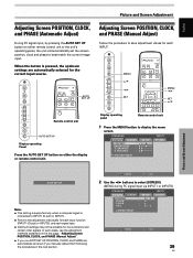
...ENHANCE : SETUP 0 0 0 0 INPUT1 OPTION PICTURE RESET Picture and Screen Adjustment AUTO SET UP Notes ÷ This setting is supported only when a computer signal is pressed, the optimum settings are automatically set the screen position, clock and phase to best match the current image input. ENHANCE : V. Display operating panel Remote control unit 1 Press the MENU button to select [SCREEN]. (MENU during PC signal input via INPUT1 or INPUT5.) S TA N D A R D PICTURE SCREEN SETUP POSITION CLOCK PHASE SIZE : 00 :0 : 0 : 00 INPUT1 OPTION SCREEN RESET SET ENTER MENU EXIT...
...ENHANCE : SETUP 0 0 0 0 INPUT1 OPTION PICTURE RESET Picture and Screen Adjustment AUTO SET UP Notes ÷ This setting is supported only when a computer signal is pressed, the optimum settings are automatically set the screen position, clock and phase to best match the current image input. ENHANCE : V. Display operating panel Remote control unit 1 Press the MENU button to select [SCREEN]. (MENU during PC signal input via INPUT1 or INPUT5.) S TA N D A R D PICTURE SCREEN SETUP POSITION CLOCK PHASE SIZE : 00 :0 : 0 : 00 INPUT1 OPTION SCREEN RESET SET ENTER MENU EXIT...
Owner's Manual
Page 52
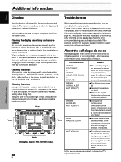
... display and remote control gently with a hard object. Do not use solvents such as a video deck. Check the Computer signal compatibility table on pages 53 to unplug the power cord from its weakest setting when doing this unit's screen to its outlet, and consult a Pioneer service center or your dealer. EN Cleaning the screen After dusting, wipe the screen gently using the supplied cleaning cloth or a soft cloth. ERROR...
... display and remote control gently with a hard object. Do not use solvents such as a video deck. Check the Computer signal compatibility table on pages 53 to unplug the power cord from its weakest setting when doing this unit's screen to its outlet, and consult a Pioneer service center or your dealer. EN Cleaning the screen After dusting, wipe the screen gently using the supplied cleaning cloth or a soft cloth. ERROR...

Owner's Manual
Page 53
... [CLAMP POSITION] setup correct? (page 25) • Is the [HDMI INPUT] setting appropriate? (Only during HDMI input) (Pages 25 to 32 and 39) • Adjust using [SCREEN] mode on the screen. • Sound is displayed in accordance with ambient conditions. Not a malfunction. • Fan speed changes automatically in a small size. • Letter breakup on ? (page 9) • External influences such as breakdown Problem • The screen is heard from...
... [CLAMP POSITION] setup correct? (page 25) • Is the [HDMI INPUT] setting appropriate? (Only during HDMI input) (Pages 25 to 32 and 39) • Adjust using [SCREEN] mode on the screen. • Sound is displayed in accordance with ambient conditions. Not a malfunction. • Fan speed changes automatically in a small size. • Letter breakup on ? (page 9) • External influences such as breakdown Problem • The screen is heard from...


