Owner's Manual
Page 12
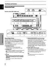
... output connector of this connector without first consulting your Pioneer installation technician. English Part Names and Functions Connection Panel Illustration depicts PRO-1010HD model. S-VIDEO INPUT3 VIDEO INPUT4 INPUT 3/4 AUDIO ANALOG RGB INPUT5 AUDIO = IN OUT R L G(ON SYNC) B R HD (H/V SYNC) VD ~! @ # R L $ Part Names and Functions R SPEAKER 8+Ω ~16Ω- 1 OUT CONTROL 2 RS-232C 3 ANALOG...
... output connector of this connector without first consulting your Pioneer installation technician. English Part Names and Functions Connection Panel Illustration depicts PRO-1010HD model. S-VIDEO INPUT3 VIDEO INPUT4 INPUT 3/4 AUDIO ANALOG RGB INPUT5 AUDIO = IN OUT R L G(ON SYNC) B R HD (H/V SYNC) VD ~! @ # R L $ Part Names and Functions R SPEAKER 8+Ω ~16Ω- 1 OUT CONTROL 2 RS-232C 3 ANALOG...

Owner's Manual
Page 13
... 18). 6 HDMI (INPUT1) (HDMI jack) For connection of the power cable to this connector, and the other component. Note The left speaker. connect one end of components that have a digital video output terminal such as a digital set top box, DVD player, etc. compatible with...) (HDMI = High Definition Multimedia Interface) 9 MAIN POWER switch Use to obtain sound when INPUT5 is selected. compatible with the plasma display; SPEAKER (L) terminal For connection of components that have a digital video output terminal such as a digital set top box, DVD player, etc. Before ...
... 18). 6 HDMI (INPUT1) (HDMI jack) For connection of the power cable to this connector, and the other component. Note The left speaker. connect one end of components that have a digital video output terminal such as a digital set top box, DVD player, etc. compatible with...) (HDMI = High Definition Multimedia Interface) 9 MAIN POWER switch Use to obtain sound when INPUT5 is selected. compatible with the plasma display; SPEAKER (L) terminal For connection of components that have a digital video output terminal such as a digital set top box, DVD player, etc. Before ...

Owner's Manual
Page 22
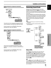
...the wire in noise or interrupted sound. ÷ Do not allow the wire cores of the selected video input is output from the SPEAKER (L/R) terminals according to the AUDIO R/L (INPUT2) pin jacks. Installation and Connections 18 EN Then, close tab firmly to the video ...input jacks Pin jacks (L/R)*1 Pin jacks (L/R) Pin jacks (L/R)*2 Pin jacks (L/R)*2 Pin jacks (L/R) Sound output Sound of the ª and · speaker cables to protrude excessively, since they may touch each other, causing a short circuit. English Installation and Connections Audio connections Before making connections, be ...
...the wire in noise or interrupted sound. ÷ Do not allow the wire cores of the selected video input is output from the SPEAKER (L/R) terminals according to the AUDIO R/L (INPUT2) pin jacks. Installation and Connections 18 EN Then, close tab firmly to the video ...input jacks Pin jacks (L/R)*1 Pin jacks (L/R) Pin jacks (L/R)*2 Pin jacks (L/R)*2 Pin jacks (L/R) Sound output Sound of the ª and · speaker cables to protrude excessively, since they may touch each other, causing a short circuit. English Installation and Connections Audio connections Before making connections, be ...
Owner's Manual
Page 23
... R/L (INPUT3/4) pin jacks is possible for the component connected to INPUT5 can then operate the connected equipment by sending commands from the SPEAKER (L/R) terminals according to the video input selection. Sound is turned off when making connections. ÷ Complete all component connections before making control... TV function). 19 EN Face the remote control units to INPUT5 of this , assign the appropriate setting on this unit and other PIONEER equipment having the Î logo. For more information, see the user's manual for INPUT1 to the remote control sensor on the ...
... R/L (INPUT3/4) pin jacks is possible for the component connected to INPUT5 can then operate the connected equipment by sending commands from the SPEAKER (L/R) terminals according to the video input selection. Sound is turned off when making connections. ÷ Complete all component connections before making control... TV function). 19 EN Face the remote control units to INPUT5 of this , assign the appropriate setting on this unit and other PIONEER equipment having the Î logo. For more information, see the user's manual for INPUT1 to the remote control sensor on the ...

Owner's Manual
Page 34
... quits muting. 30 EN fH : 48. 4 kH z fV : 60. 0 H z 1024X768 D-SUB DOT BY DOT Note The displayed refresh rates may be slightly different from the speakers. Press the [-] or [+] button to restore the sound.
... quits muting. 30 EN fH : 48. 4 kH z fV : 60. 0 H z 1024X768 D-SUB DOT BY DOT Note The displayed refresh rates may be slightly different from the speakers. Press the [-] or [+] button to restore the sound.
Owner's Manual
Page 55
English Specifications General (PRO-1010HD) Light emission panel 50-inch AC Plasma Panel 109.8 (W) x 62..., VD ... Weight 39 kg (86 lbs.) Operating temperature range ....... 0 to 40 °C (32 to 104°F) General (PRO-810HD) Light emission panel 43-inch AC Plasma Panel 95.2 (W) x 53.6 (H) x 109.3 (diagonal) cm Number of pixels ...Pin jack (x2) L/R ... 500mVrms/more than 10 kΩ AUDIO INPUT (for INPUT5) Pin jack (x2) L/R ... 500mVrms/more than 10 kΩ Output SPEAKER L/R ... 8 - 16 Ω/7 W +7 W (at 8 Ω) Control RS-232C ... C . . . 0.286 Vp-p/75 Ω (NTSC) ...
English Specifications General (PRO-1010HD) Light emission panel 50-inch AC Plasma Panel 109.8 (W) x 62..., VD ... Weight 39 kg (86 lbs.) Operating temperature range ....... 0 to 40 °C (32 to 104°F) General (PRO-810HD) Light emission panel 43-inch AC Plasma Panel 95.2 (W) x 53.6 (H) x 109.3 (diagonal) cm Number of pixels ...Pin jack (x2) L/R ... 500mVrms/more than 10 kΩ AUDIO INPUT (for INPUT5) Pin jack (x2) L/R ... 500mVrms/more than 10 kΩ Output SPEAKER L/R ... 8 - 16 Ω/7 W +7 W (at 8 Ω) Control RS-232C ... C . . . 0.286 Vp-p/75 Ω (NTSC) ...


