Owner's Manual
Page 4
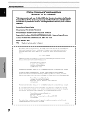
... la garantie, veuillez vous reporter au feuillet sur la garantie restreinte qui accompagne le produit. Pioneer Electronics (USA) Inc. S018_A_EF iivi EN Safety Precautions Operation is subject to purchase replacement parts, operating instructions, service manuals, or accessories, please call the number shown below. 8 0 0 - 4 2 ... that may cause undesired operation. Product Name: Plasma Display Model Number: PRO-1010HD / PRO-810HD Product Category: Class B Personal Computers & Peripherals Responsible Party Name: PIONEER ELECTRONICS [USA] INC. BOX 1760, Long Beach, CA 90801-1760, U.S.A.
... la garantie, veuillez vous reporter au feuillet sur la garantie restreinte qui accompagne le produit. Pioneer Electronics (USA) Inc. S018_A_EF iivi EN Safety Precautions Operation is subject to purchase replacement parts, operating instructions, service manuals, or accessories, please call the number shown below. 8 0 0 - 4 2 ... that may cause undesired operation. Product Name: Plasma Display Model Number: PRO-1010HD / PRO-810HD Product Category: Class B Personal Computers & Peripherals Responsible Party Name: PIONEER ELECTRONICS [USA] INC. BOX 1760, Long Beach, CA 90801-1760, U.S.A.

Owner's Manual
Page 5
... 1 EN Note for Dealers: After installation, be sure to operate the Plasma Display properly. You will know how to deliver this PIONEER product. PIONEER cannot assume liabilities for purchasing this manual to the customer and explain to the customer how to the Original Picture Adjustment Values 38 Adjusting Screen POSITION, CLOCK, and PHASE...
... 1 EN Note for Dealers: After installation, be sure to operate the Plasma Display properly. You will know how to deliver this PIONEER product. PIONEER cannot assume liabilities for purchasing this manual to the customer and explain to the customer how to the Original Picture Adjustment Values 38 Adjusting Screen POSITION, CLOCK, and PHASE...
Owner's Manual
Page 6
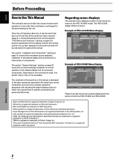
...components. Regarding menu displays The example menu displays provided in this manual is dedicated to the basic operations associated with selecting a source component up this manual. NEC and PC-9800 are those for the PRO-1010HD model. HDMI, the HDMI logo and High-Definition Multimedia Interface are... the same for both the PRO-1010HD and PRO-810HD. The PRO-810HD display differs as their respective buttons and ...
...components. Regarding menu displays The example menu displays provided in this manual is dedicated to the basic operations associated with selecting a source component up this manual. NEC and PC-9800 are those for the PRO-1010HD model. HDMI, the HDMI logo and High-Definition Multimedia Interface are... the same for both the PRO-1010HD and PRO-810HD. The PRO-810HD display differs as their respective buttons and ...
Owner's Manual
Page 7
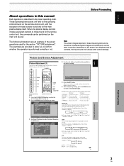
English About operations in this manual Each operation is described in the picture when viewing a digital broadcast, playing a DVD etc. When the plasma display controls include equivalent buttons to those buttons ...
English About operations in this manual Each operation is described in the picture when viewing a digital broadcast, playing a DVD etc. When the plasma display controls include equivalent buttons to those buttons ...
Owner's Manual
Page 14
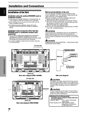
...and possible fire hazard, make sure that can be inserted 1/2 inch (12 mm) to the instruction manual provided with bolt holes for securing the unit. 10 EN Also, as a wall interface for wallmount ...and Connections Installation of the Unit Installation using the optional PIONEER stand or installation bracket ÷ Please be sure to request installation or mounting... custom installation, please consult the dealer where the unit was purchased.) 1 Table top stand : PRO-1010HD / PRO-810HD display stand. 2 Wall installation unit : Wall installation bracket designed as hot air is constructed...
...and possible fire hazard, make sure that can be inserted 1/2 inch (12 mm) to the instruction manual provided with bolt holes for securing the unit. 10 EN Also, as a wall interface for wallmount ...and Connections Installation of the Unit Installation using the optional PIONEER stand or installation bracket ÷ Please be sure to request installation or mounting... custom installation, please consult the dealer where the unit was purchased.) 1 Table top stand : PRO-1010HD / PRO-810HD display stand. 2 Wall installation unit : Wall installation bracket designed as hot air is constructed...

Owner's Manual
Page 18
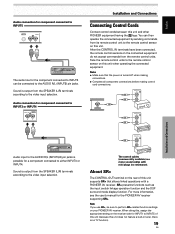
... RGB IN D-Sub IINNPPUUTT11 AUDIO R L HDMI Installation and Connections 14 EN On-screen setup is necessary after connection. For details, please read your PC's instruction manual or consult the maker or nearest dealer of the green signal. Please see pages 23 to the VD or HD jacks. Please see pages 23...
... RGB IN D-Sub IINNPPUUTT11 AUDIO R L HDMI Installation and Connections 14 EN On-screen setup is necessary after connection. For details, please read your PC's instruction manual or consult the maker or nearest dealer of the green signal. Please see pages 23 to the VD or HD jacks. Please see pages 23...

Owner's Manual
Page 21
... with the DTV set top box. English Installation and Connections About DTV Set Top Box Connection To ensure proper connection, please carefully read the instruction manual supplied with are as follows.
... with the DTV set top box. English Installation and Connections About DTV Set Top Box Connection To ensure proper connection, please carefully read the instruction manual supplied with are as follows.
Owner's Manual
Page 23
...the power is output from the remote control units. The control cables (commercially available) are mono sound cables with a PIONEER AV receiver. For more information, see the user's manual for component connected to the AUDIO R/L (INPUT5) pin jacks. You can be sure to perform SR+ related function... settings on your PIONEER AV receiver. CONTROL IN SR OUT OUT CONTROL CONTROL IN SR OUT Installation and Connections ...
...the power is output from the remote control units. The control cables (commercially available) are mono sound cables with a PIONEER AV receiver. For more information, see the user's manual for component connected to the AUDIO R/L (INPUT5) pin jacks. You can be sure to perform SR+ related function... settings on your PIONEER AV receiver. CONTROL IN SR OUT OUT CONTROL CONTROL IN SR OUT Installation and Connections ...
Owner's Manual
Page 27
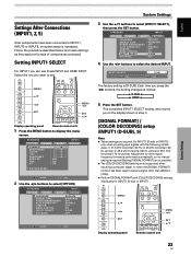
... when inputting a computer signal, or when the [SIGNAL FORMAT] function has been used to select a signal other signal frequency formats is performed automatically, so no manual setting is required (Setting [SIGNAL FORMAT] is not possible). ÷ The [COLOR DECODING] setting is necessary. MENU 5/∞ 2/3 SET MENU 2/3 SET 5/∞ Display operating panel...
... when inputting a computer signal, or when the [SIGNAL FORMAT] function has been used to select a signal other signal frequency formats is performed automatically, so no manual setting is required (Setting [SIGNAL FORMAT] is not possible). ÷ The [COLOR DECODING] setting is necessary. MENU 5/∞ 2/3 SET MENU 2/3 SET 5/∞ Display operating panel...
Owner's Manual
Page 28
... of 48.4 kHz horizontal / 60 Hz vertical, or 56.1 kHz horizontal / 70 Hz vertical, pressing 2/3 will cause the screen resolution to be set [SIGNAL FORMAT] manually to select the display mode.
... of 48.4 kHz horizontal / 60 Hz vertical, or 56.1 kHz horizontal / 70 Hz vertical, pressing 2/3 will cause the screen resolution to be set [SIGNAL FORMAT] manually to select the display mode.
Owner's Manual
Page 29
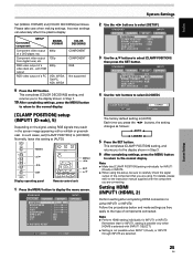
... COLOR DECODING COMPONENT COMPONENT RGB Not supported 9 Press the SET button. Remember that you are connecting. In such cases, set [CLAMP POSITION] to the instruction manual supplied with RGB output RGB video output of components connected. Notes ÷ Make this [CLAMP POSITION] setting individually for INPUT1 or INPUT2. Notes ÷ Perform...
... COLOR DECODING COMPONENT COMPONENT RGB Not supported 9 Press the SET button. Remember that you are connecting. In such cases, set [CLAMP POSITION] to the instruction manual supplied with RGB output RGB video output of components connected. Notes ÷ Make this [CLAMP POSITION] setting individually for INPUT1 or INPUT2. Notes ÷ Perform...

Owner's Manual
Page 30
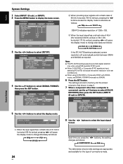
...], then press the SET button. COLOR1: Accepts Y CB/PB CR/PR (4 : 2 : 2) signals. In this event, select COLOR1, COLOR2, COLOR3 or COLOR4 manually in accordance with some input signals. S TA N D A R D INPUT1 PICTURE SCREEN SETUP PURECINEMA : OFF CLAMP POSITION : SIGNAL FORMAT : COLOR DECODING : HDMI ...Press the SET button. English System Settings PICTURE SELECT This function allows you to switch the input signal format to automatic or manual when inputting the digital signal. 1 Press the MENU button to remove white glare in the picture when accepts RGB signals. COLOR2...
...], then press the SET button. COLOR1: Accepts Y CB/PB CR/PR (4 : 2 : 2) signals. In this event, select COLOR1, COLOR2, COLOR3 or COLOR4 manually in accordance with some input signals. S TA N D A R D INPUT1 PICTURE SCREEN SETUP PURECINEMA : OFF CLAMP POSITION : SIGNAL FORMAT : COLOR DECODING : HDMI ...Press the SET button. English System Settings PICTURE SELECT This function allows you to switch the input signal format to automatic or manual when inputting the digital signal. 1 Press the MENU button to remove white glare in the picture when accepts RGB signals. COLOR2...

Owner's Manual
Page 31
... OPTION PICTURE RESET SET ENTER MENU EXIT System Settings 27 EN English AUDIO This function allows you to switch the audio signal to automatic or manual when inputting the digital signal. 1 Press the MENU button to select [AUDIO]. S TA N D A R D INPUT2 PICTURE SCREEN SETUP ...+MODE setting is selected, automatic switching may not occur properly with the actual signal input. 6 Press the SET button. In this unit to connect another Pioneer product (Refer to page 19 for connection details). 1 Press the MENU button to select [AUDIO] setting. S TA N D A R D INPUT2 PICTURE...
... OPTION PICTURE RESET SET ENTER MENU EXIT System Settings 27 EN English AUDIO This function allows you to switch the audio signal to automatic or manual when inputting the digital signal. 1 Press the MENU button to select [AUDIO]. S TA N D A R D INPUT2 PICTURE SCREEN SETUP ...+MODE setting is selected, automatic switching may not occur properly with the actual signal input. 6 Press the SET button. In this unit to connect another Pioneer product (Refer to page 19 for connection details). 1 Press the MENU button to select [AUDIO] setting. S TA N D A R D INPUT2 PICTURE...

Owner's Manual
Page 41
... press the 2/3 buttons, the setting changes as shown below. HIGH, G. LOW adjustment values are not reflected if anything other than MANUAL/** is saved. ¶ Setting items during PC signal input GRADATION This function sets picture γ characteristics. HIGH, B. Provides a... mode. Adjusts the blue of bright parts R. LOW or B. HIGH, G. The following functions make fine adjustments to MANUAL/ **. ÷ R. HIGH ... LOW ... HIGH ... MANUAL/** is selected. Provides standard brightness γ characteristics. ¶ GAMMA2.2 ... HIGH ... Adjusts the red of dark ...
... press the 2/3 buttons, the setting changes as shown below. HIGH, G. LOW adjustment values are not reflected if anything other than MANUAL/** is saved. ¶ Setting items during PC signal input GRADATION This function sets picture γ characteristics. HIGH, B. Provides a... mode. Adjusts the blue of bright parts R. LOW or B. HIGH, G. The following functions make fine adjustments to MANUAL/ **. ÷ R. HIGH ... LOW ... HIGH ... MANUAL/** is selected. Provides standard brightness γ characteristics. ¶ GAMMA2.2 ... HIGH ... Adjusts the red of dark ...
Owner's Manual
Page 43
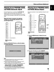
AUTO SET UP Adjusting Screen POSITION, CLOCK, and PHASE (Manual Adjust) Follow the procedure to select [SCREEN]. (MENU during PC signal input via INPUT1 or INPUT5.) S TA N D A R D PICTURE SCREEN SETUP POSITION CLOCK PHASE SIZE : 00 :0 : 0 : ... panel Remote control unit 1 Press the MENU button to INPUT1 (D-sub) or INPUT5. ÷ Perform this page, "Adjusting Screen POSITION, CLOCK, and PHASE (Manual Adjust)". ÷ If you manually adjust them following the procedures in the next section. In such cases, use the adjustment methods explained on either remote control unit or...
AUTO SET UP Adjusting Screen POSITION, CLOCK, and PHASE (Manual Adjust) Follow the procedure to select [SCREEN]. (MENU during PC signal input via INPUT1 or INPUT5.) S TA N D A R D PICTURE SCREEN SETUP POSITION CLOCK PHASE SIZE : 00 :0 : 0 : ... panel Remote control unit 1 Press the MENU button to INPUT1 (D-sub) or INPUT5. ÷ Perform this page, "Adjusting Screen POSITION, CLOCK, and PHASE (Manual Adjust)". ÷ If you manually adjust them following the procedures in the next section. In such cases, use the adjustment methods explained on either remote control unit or...


