User Guide
Page 2
... is a registered trademark of American Megatrends Inc. AMI® is a registered trademark of Novell, Inc. Visit the MSI website for FAQ, technical guide, BIOS updates, driver updates, and other countries. PS/2 and OS®/2 are registered trademarks of Intel Corporation. Revision History ..., DualNet, and nForce are registered trademarks or trademarks of NVIDIA Corporation in the United States and/or other information: http://global.msi.com.tw/index.php? Intel® and Pentium® are registered trademarks of International Business Machines Corporation. Award® is ...
... is a registered trademark of American Megatrends Inc. AMI® is a registered trademark of Novell, Inc. Visit the MSI website for FAQ, technical guide, BIOS updates, driver updates, and other countries. PS/2 and OS®/2 are registered trademarks of Intel Corporation. Revision History ..., DualNet, and nForce are registered trademarks or trademarks of NVIDIA Corporation in the United States and/or other information: http://global.msi.com.tw/index.php? Intel® and Pentium® are registered trademarks of International Business Machines Corporation. Award® is ...
User Guide
Page 8
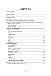
... Supply ...2-8 Back Panel ...2-10 Connectors ...2-12 Button ...2-19 Slots ...2-20 LED Status Indicators 2-25 Chapter 3 BIOS Setup 3-1 Entering Setup ...3-2 The Main Menu ...3-4 Standard CMOS Features 3-6 Advanced BIOS Features 3-8 Integrated Peripherals 3-11 Power Management Setup 3-13 H/W Monitor ...3-16 BIOS Setting Password 3-17 Cell Menu ...3-18 USERSETTINGS 3-23 Load Fail-Safe/ Optimized Defaults 3-24 Appendix...
... Supply ...2-8 Back Panel ...2-10 Connectors ...2-12 Button ...2-19 Slots ...2-20 LED Status Indicators 2-25 Chapter 3 BIOS Setup 3-1 Entering Setup ...3-2 The Main Menu ...3-4 Standard CMOS Features 3-6 Advanced BIOS Features 3-8 Integrated Peripherals 3-11 Power Management Setup 3-13 H/W Monitor ...3-16 BIOS Setting Password 3-17 Cell Menu ...3-18 USERSETTINGS 3-23 Load Fail-Safe/ Optimized Defaults 3-24 Appendix...
User Guide
Page 9
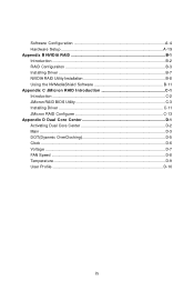
Software Configuration A-4 Hardware Setup A-19 Appendix B NVIDIA RAID B-1 Introduction ...B-2 RAID Configuraiton B-3 Installing Driver ...B-7 NVIDIA RAID Utility Installation B-8 Using the NVMediaShield Software B-11 Appendix C JM icron RAID Introduction C-1 Introduction ...C-2 JMicron RAID BIOS Utility C-3 Installing Driver C-11 JMicron RAID Configurer C-13 Appendix D Dual Core Center D-1 Activating Dual Core Center D-2 Main ...D-3 DOT(Dyanmic OverClocking D-5 Clock ...D-6 Voltage ...D-7 FAN Speed ...D-8 Temperature ...D-9 User Profile ...D-10 ix
Software Configuration A-4 Hardware Setup A-19 Appendix B NVIDIA RAID B-1 Introduction ...B-2 RAID Configuraiton B-3 Installing Driver ...B-7 NVIDIA RAID Utility Installation B-8 Using the NVMediaShield Software B-11 Appendix C JM icron RAID Introduction C-1 Introduction ...C-2 JMicron RAID BIOS Utility C-3 Installing Driver C-11 JMicron RAID Configurer C-13 Appendix D Dual Core Center D-1 Activating Dual Core Center D-2 Main ...D-3 DOT(Dyanmic OverClocking D-5 Clock ...D-6 Voltage ...D-7 FAN Speed ...D-8 Temperature ...D-9 User Profile ...D-10 ix
User Guide
Page 19
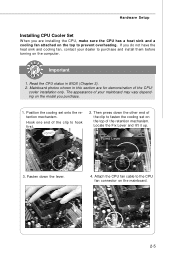
... dealer to purchase and install them before turning on the top of the retention mechanism. Important 1. If you purchase. 1. Fixed Lever 3. Mainboard photos shown in BIOS (Chapter 3). 2. Fasten down the other end of the clip to prevent overheating. Position the cooling set on the computer. Read the CPU status in this...
... dealer to purchase and install them before turning on the top of the retention mechanism. Important 1. If you purchase. 1. Fixed Lever 3. Mainboard photos shown in BIOS (Chapter 3). 2. Fasten down the other end of the clip to prevent overheating. Position the cooling set on the computer. Read the CPU status in this...
User Guide
Page 29
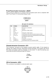
... connector is compliant with Intel® Front Panel I/O Connectivity Design Guide. Hardware Setup Front Panel Audio Connector: JAUD1 This connector allows you must enter the BIOS utility and clear the record. Right channel Jack detection return from front panel microphone JACK1 Jack detection sense line from front panel JACK2 Chassis Intrusion...
... connector is compliant with Intel® Front Panel I/O Connectivity Design Guide. Hardware Setup Front Panel Audio Connector: JAUD1 This connector allows you must enter the BIOS utility and clear the record. Right channel Jack detection return from front panel microphone JACK1 Jack detection sense line from front panel JACK2 Chassis Intrusion...
User Guide
Page 34
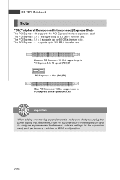
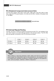
... 8.0 GB/s transfer rate. The PCI Express x 1 supports up to configure any necessary hardware or software settings for the expansion card, such as jumpers, switches or BIOS configuration. 2-20 The PCI Express 2.0 x 16 supports up to 4.0 GB/s transfer rate. MS-7374 Mainboard Slots PCI (Peripheral Component Interconnect) Express Slots The PCI Express...
... 8.0 GB/s transfer rate. The PCI Express x 1 supports up to configure any necessary hardware or software settings for the expansion card, such as jumpers, switches or BIOS configuration. 2-20 The PCI Express 2.0 x 16 supports up to 4.0 GB/s transfer rate. MS-7374 Mainboard Slots PCI (Peripheral Component Interconnect) Express Slots The PCI Express...
User Guide
Page 37
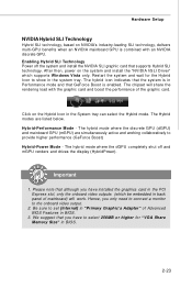
...for "VGA Share Memory Size" in back panel of Advanced BIOS Features in the System tray can select the Hybird mode. Hardware Setup NVIDIA Hybrid SLI Technology Hybrid SLI technology, based on NVIDIA's industry-leading SLI technology, delivers multi-GPU benefits when an NVIDIA mainboard GPU... is enabled. After then, power on the Hybrid Icon in BIOS. 3. Click on the system and install ...
...for "VGA Share Memory Size" in back panel of Advanced BIOS Features in the System tray can select the Hybird mode. Hardware Setup NVIDIA Hybrid SLI Technology Hybrid SLI technology, based on NVIDIA's industry-leading SLI technology, delivers multi-GPU benefits when an NVIDIA mainboard GPU... is enabled. After then, power on the Hybrid Icon in BIOS. 3. Click on the system and install ...
User Guide
Page 38
... supply first. The PCI IRQ pins are hardware lines over which devices can send interrupt signals to the PCI bus pins as jumpers, switches or BIOS configuration. 2-24
... supply first. The PCI IRQ pins are hardware lines over which devices can send interrupt signals to the PCI bus pins as jumpers, switches or BIOS configuration. 2-24
User Guide
Page 40
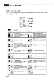
...Group2 Group1 Early Chipset Initialization Group4 Group3 Group2 Group1 Memory Detection Test Testing onboard memory size. Group4 Group3 Group2 Group1 BIOS Sign On This will start showing information about logo, processor brand name, etc... LED Signal Description Group4 Group3 Group2...detecting CPU clock, checking type ofvideo onboard. Group4 Group3 Group2 Group1 Operating System Booting Group4 Group3 Group2 Group1 Decompressing BIOS image to identify system problems through 16 various combinations of LED signals. Group4 Group3 Group2 Group1 BootAttempt This will...
...Group2 Group1 Early Chipset Initialization Group4 Group3 Group2 Group1 Memory Detection Test Testing onboard memory size. Group4 Group3 Group2 Group1 BIOS Sign On This will start showing information about logo, processor brand name, etc... LED Signal Description Group4 Group3 Group2...detecting CPU clock, checking type ofvideo onboard. Group4 Group3 Group2 Group1 Operating System Booting Group4 Group3 Group2 Group1 Decompressing BIOS image to identify system problems through 16 various combinations of LED signals. Group4 Group3 Group2 Group1 BootAttempt This will...
User Guide
Page 41
You may need to run the Setup program when: ² An error message appears on the BIOS Setup program and allows you to run SETUP. ² You want to configure the system for customized features. 3-1 Chapter 3 BIOS Setup BIOS Setup This chapter provides information on the screen during the system booting up, and requests you to change the default settings for optimum use.
You may need to run the Setup program when: ² An error message appears on the BIOS Setup program and allows you to run SETUP. ² You want to configure the system for customized features. 3-1 Chapter 3 BIOS Setup BIOS Setup This chapter provides information on the screen during the system booting up, and requests you to change the default settings for optimum use.
User Guide
Page 42
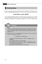
Upon boot-up, the 1st line appearing after the memory count is usually in this BIOS was released. 3-2 It is the BIOS version. You may be slightly different from the latest BIOS and should be held for better system performance. Press DEL to enter SETUP If the message disappears before you... Power on the screen, press key to enter Setup. V1.0 refers to the BIOS version. 021308 refers to the date this chapter are under each BIOS category described in the format: A7374NMS V1.0 021308 where: 1st digit refers to BIOS maker as A = AMI, W = AWARD, and P = PHOENIX. 2nd - 5th digit ...
Upon boot-up, the 1st line appearing after the memory count is usually in this BIOS was released. 3-2 It is the BIOS version. You may be slightly different from the latest BIOS and should be held for better system performance. Press DEL to enter SETUP If the message disappears before you... Power on the screen, press key to enter Setup. V1.0 refers to the BIOS version. 021308 refers to the date this chapter are under each BIOS category described in the format: A7374NMS V1.0 021308 where: 1st digit refers to BIOS maker as A = AMI, W = AWARD, and P = PHOENIX. 2nd - 5th digit ...
User Guide
Page 43
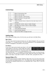
... right hand Select the item Jumps to the Exit menu or returns to the main menu from any menu by simply pressing . General Help The BIOS setup program provides a General Help screen. The on-line description of the highlighted setup function is the Main Menu. Sub-M enu If you can be... launched from this screen from a submenu Increase the numeric value or make changes Decrease the numeric value or make changes to. BIOS Setup Control Keys Enter> Move to the previous item Move to the next item Move to the item in the left hand Move to the...
... right hand Select the item Jumps to the Exit menu or returns to the main menu from any menu by simply pressing . General Help The BIOS setup program provides a General Help screen. The on-line description of the highlighted setup function is the Main Menu. Sub-M enu If you can be... launched from this screen from a submenu Increase the numeric value or make changes Decrease the numeric value or make changes to. BIOS Setup Control Keys Enter> Move to the previous item Move to the next item Move to the item in the left hand Move to the...
User Guide
Page 44
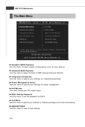
Advanced BIOS Features Use this menu to specify your settings for frequency/voltage control and overclocking. Power Management Setup Use this menu to setup the items of ... entry shows your settings for basic system configurations, such as time, date etc. Cell Menu Use this menu to set the password for power management. BIOS Setting Password Use this menu to specify your PC health status. Integrated Peripherals Use this menu to specify your settings for...
Advanced BIOS Features Use this menu to specify your settings for frequency/voltage control and overclocking. Power Management Setup Use this menu to setup the items of ... entry shows your settings for basic system configurations, such as time, date etc. Cell Menu Use this menu to set the password for power management. BIOS Setting Password Use this menu to specify your PC health status. Integrated Peripherals Use this menu to specify your settings for...

User Guide
Page 45
Load Optimized Defaults Use this menu to load the default values set by the BIOS vendor for optimal performance of the mainboard. BIOS Setup Load Fail-Safe Defaults Use this menu to load the default values set by the mainboard manufacturer specifically for stable system performance. Exit Without Saving Abandon all changes and exit setup. 3-5 Save & Exit Setup Save changes to CMOS and exit setup.
Load Optimized Defaults Use this menu to load the default values set by the BIOS vendor for optimal performance of the mainboard. BIOS Setup Load Fail-Safe Defaults Use this menu to load the default values set by the mainboard manufacturer specifically for stable system performance. Exit Without Saving Abandon all changes and exit setup. 3-5 Save & Exit Setup Save changes to CMOS and exit setup.
User Guide
Page 46
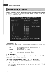
... Features Menu includes some basic setup items. Use the arrow keys to highlight the item and then use the or keys to Sat, determined by BIOS. Date (MM:DD:YY) This allows you to set the system time that you want (usually the current date). day Day of the week, from...
... Features Menu includes some basic setup items. Use the arrow keys to highlight the item and then use the or keys to Sat, determined by BIOS. Date (MM:DD:YY) This allows you to set the system time that you want (usually the current date). day Day of the week, from...
User Guide
Page 47
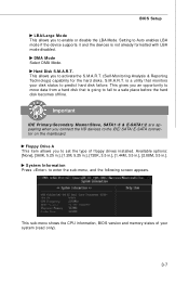
... hard disk becomes offline. This gives you an opportunity to move data from a hard disk that monitors your system (read only). 3-7 Hard Disk S.M.A.R.T. BIOS Setup LBA/Large M ode This allows you to predict hard disk failure. S.M.A.R.T. is not already formatted with LBA mode disabled. DM A M ode Select...allows you connect the HD devices to enter the sub-menu, and the following screen appears. This sub-menu shows the CPU information, BIOS version and memory status of floppy drives installed. Setting to set the type of your disk status to enable or disable the LBA Mode....
... hard disk becomes offline. This gives you an opportunity to move data from a hard disk that monitors your system (read only). 3-7 Hard Disk S.M.A.R.T. BIOS Setup LBA/Large M ode This allows you to predict hard disk failure. S.M.A.R.T. is not already formatted with LBA mode disabled. DM A M ode Select...allows you connect the HD devices to enter the sub-menu, and the following screen appears. This sub-menu shows the CPU information, BIOS version and memory status of floppy drives installed. Setting to set the type of your disk status to enable or disable the LBA Mode....
User Guide
Page 48
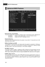
... the APIC (Advanced Programmable Interrupt Controller). Enabling APIC mode will allow users to use , consult the vendor of your operating system. MS-7374 Mainboard Advanced BIOS Features Full Screen Logo Display This item enables you to select which version to use the arrow keys on the numeric keypad. Due to [Off...
... the APIC (Advanced Programmable Interrupt Controller). Enabling APIC mode will allow users to use , consult the vendor of your operating system. MS-7374 Mainboard Advanced BIOS Features Full Screen Logo Display This item enables you to select which version to use the arrow keys on the numeric keypad. Due to [Off...
User Guide
Page 49
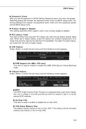
...which graphic card is part of the chipset. For better PCI performance, you should set to higher values. BIOS Setup Password Check After you set the password in BIOS Setting Password menu, this item will request the password when enter both the operating system and the... BIOS setup menu. Selecting [setup] will provide you with the means to get to the on -chip VGA. ...VGA Share Memory Size The system shares memory to it , and will request the password when enter the BIOS setup menu.
...which graphic card is part of the chipset. For better PCI performance, you should set to higher values. BIOS Setup Password Check After you set the password in BIOS Setting Password menu, this item will request the password when enter both the operating system and the... BIOS setup menu. Selecting [setup] will provide you with the means to get to the on -chip VGA. ...VGA Share Memory Size The system shares memory to it , and will request the password when enter the BIOS setup menu.
User Guide
Page 50
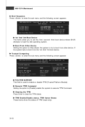
... sub-menu and the following screen appears: 1st/ 2nd/ 3rd Boot Device The items allow you to set the first/ second/ third boot device where BIOS attempts to clear the TPM status. MS-7374 Mainboard Boot Sequence Press to enter the sub-menu and the following screen appears TCG/TPM SUPPORT...
... sub-menu and the following screen appears: 1st/ 2nd/ 3rd Boot Device The items allow you to set the first/ second/ third boot device where BIOS attempts to clear the TPM status. MS-7374 Mainboard Boot Sequence Press to enter the sub-menu and the following screen appears TCG/TPM SUPPORT...
User Guide
Page 51
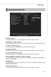
... (IDE2, ESATA1 and E-SATA2). LAN Option ROM This item is used to decide whether to invoke the Boot ROM of the LAN controller. Integrated Peripherals BIOS Setup USB Controller This setting allows you to select the RAID function for JM icron RAID) This item allows you to enable/disable the onboard...
... (IDE2, ESATA1 and E-SATA2). LAN Option ROM This item is used to decide whether to invoke the Boot ROM of the LAN controller. Integrated Peripherals BIOS Setup USB Controller This setting allows you to select the RAID function for JM icron RAID) This item allows you to enable/disable the onboard...


