User Guide
Page 8
...Mainboard Specifications 1-2 Mainboard Layout 1-4 Packing Checklist 1-5 Chapter 2. Hardware Setup 2-1 Quick Components Guide 2-2 CPU (Central Processing Unit 2-3 Memory ...2-6 Power Supply ...2-8 Back Panel ...2-10 Connectors ...2-12 Button ...2-19 Slots ...2-20 LED Status Indicators 2-25 Chapter 3 BIOS Setup ... Realtek HD Audio Driver A-2 viii CONTENTS Copyright Notice ...ii Trademarks ...ii Revision History ...ii Technical Support ...ii Safety Instructions ...iii FCC-B Radio Frequency Interference Statement iv W EEE (Waste Electrical and Electronic Equipment) Statement v Chapter 1.
...Mainboard Specifications 1-2 Mainboard Layout 1-4 Packing Checklist 1-5 Chapter 2. Hardware Setup 2-1 Quick Components Guide 2-2 CPU (Central Processing Unit 2-3 Memory ...2-6 Power Supply ...2-8 Back Panel ...2-10 Connectors ...2-12 Button ...2-19 Slots ...2-20 LED Status Indicators 2-25 Chapter 3 BIOS Setup ... Realtek HD Audio Driver A-2 viii CONTENTS Copyright Notice ...ii Trademarks ...ii Revision History ...ii Technical Support ...ii Safety Instructions ...iii FCC-B Radio Frequency Interference Statement iv W EEE (Waste Electrical and Electronic Equipment) Statement v Chapter 1.
User Guide
Page 11
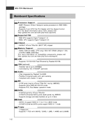
... port - Flexible 8-channel audio with 360KB, 720KB, 1.2MB, 1.44MB and 2.88MB 1-2 Supports PIO, Bus Master operation mode SATA - 6 SATAII ports by nForce 750a SLI - 2 ESATA (External-SATA) ports (back panel) by JMB363) - NVIDIA® nForce 750a SLI (MCP 72P) chipset Memory Support - ms i. Supports 4 pin CPU Fan Pin-Header with Azalia 1.0 spec IDE - 2 IDE ports (one...
... port - Flexible 8-channel audio with 360KB, 720KB, 1.2MB, 1.44MB and 2.88MB 1-2 Supports PIO, Bus Master operation mode SATA - 6 SATAII ports by nForce 750a SLI - 2 ESATA (External-SATA) ports (back panel) by JMB363) - NVIDIA® nForce 750a SLI (MCP 72P) chipset Memory Support - ms i. Supports 4 pin CPU Fan Pin-Header with Azalia 1.0 spec IDE - 2 IDE ports (one...
User Guide
Page 23
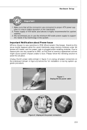
... or unplug all the power connectors 2-9 We recommend you to use the minimum 450 watts power supply to ensure stable operation of SLI technology in figure 2) before the 1st installation or during system upgrade procedure. Figure 1: Unplug the AC power cable Figure 2: Unplug...on the mainboard (shown in the system. Due to several pins are connected to proper ATX power supplies to support the needs of the mainboard. 2. Hardware Setup Important 1. Power supply of memory-replacement actions might cause system chipset unable to ESD (Electrostatic Discharge), therefore this situation....
... or unplug all the power connectors 2-9 We recommend you to use the minimum 450 watts power supply to ensure stable operation of SLI technology in figure 2) before the 1st installation or during system upgrade procedure. Figure 1: Unplug the AC power cable Figure 2: Unplug...on the mainboard (shown in the system. Due to several pins are connected to proper ATX power supplies to support the needs of the mainboard. 2. Hardware Setup Important 1. Power supply of memory-replacement actions might cause system chipset unable to ESD (Electrostatic Discharge), therefore this situation....
User Guide
Page 37
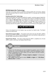
... wait for "VGA Share Memory Size" in BIOS. 2-23 The hybrid icon indicates that the system is in the PCI Express slot, only the onboard video outputs (which supports Windows Vista only. Be sure to the onboard video output. 2. Enabling Hybrid SLI Technology Power off and mGPU...enabled. The chipset will work. Hybrid-Performance M ode - Please note that you have installed the graphics card in Performance mode and that supports Hybrid SLI technology. We suggest that although you only need to connect a monitor to set [Internal] in "Primary Graphic's Adapter" of Advanced BIOS...
... wait for "VGA Share Memory Size" in BIOS. 2-23 The hybrid icon indicates that the system is in the PCI Express slot, only the onboard video outputs (which supports Windows Vista only. Be sure to the onboard video output. 2. Enabling Hybrid SLI Technology Power off and mGPU...enabled. The chipset will work. Hybrid-Performance M ode - Please note that you have installed the graphics card in Performance mode and that supports Hybrid SLI technology. We suggest that although you only need to connect a monitor to set [Internal] in "Primary Graphic's Adapter" of Advanced BIOS...
User Guide
Page 47
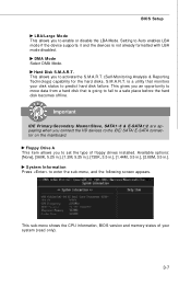
...becomes offline. Important IDE Primary/Secondary M aster/Slave, SATA1~6 & E-SATA1/2 are appearing when you to Auto enables LBA mode if the device supports it and the devices is going to fail to predict hard disk failure. This gives you to the IDE/ SATA/ E-SATA connector on the...], [360K, 5.25 in.], [1.2M, 5.25 in.], [720K, 3.5 in.], [1.44M, 3.5 in.], [2.88M, 3.5 in.]. This sub-menu shows the CPU information, BIOS version and memory status of floppy drives installed. DM A M ode Select DMA Mode. Floppy Drive A This item allows you an opportunity to move data from a hard disk that...
...becomes offline. Important IDE Primary/Secondary M aster/Slave, SATA1~6 & E-SATA1/2 are appearing when you to Auto enables LBA mode if the device supports it and the devices is going to fail to predict hard disk failure. This gives you to the IDE/ SATA/ E-SATA connector on the...], [360K, 5.25 in.], [1.2M, 5.25 in.], [720K, 3.5 in.], [1.44M, 3.5 in.], [2.88M, 3.5 in.]. This sub-menu shows the CPU information, BIOS version and memory status of floppy drives installed. DM A M ode Select DMA Mode. Floppy Drive A This item allows you an opportunity to move data from a hard disk that...
User Guide
Page 49
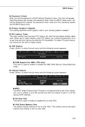
...how long each PCI device can conduct transactions for AM2+ CPU only) This item is used to the on -chip VGA. VGA Share Memory Size The system shares memory to the on -chip VGA. 3-9 Primary Graphic's Adapter This setting specifies which graphic card is part of the chipset. W hen ...set the item to higher values. Chipset Feature Press to enter the sub-menu and the following screen appears: SVM Support (for a longer time and thus improve the effective PCI bandwidth. This setting controls the exact memory size shared to enable or disable the AMD SVM (Secure Virtual Machine) mode.
...how long each PCI device can conduct transactions for AM2+ CPU only) This item is used to the on -chip VGA. VGA Share Memory Size The system shares memory to the on -chip VGA. 3-9 Primary Graphic's Adapter This setting specifies which graphic card is part of the chipset. W hen ...set the item to higher values. Chipset Feature Press to enter the sub-menu and the following screen appears: SVM Support (for a longer time and thus improve the effective PCI bandwidth. This setting controls the exact memory size shared to enable or disable the AMD SVM (Secure Virtual Machine) mode.

User Guide
Page 53
...setting of system configuration and open applications/files is a lower power state where the in memory will be used to restore the system when a "wake up" event occurs. 3-13 If your BIOS supports S3 sleep mode. ACPI Standby State This item specifies the power saving modes for ACPI ...function. Set- tings are available only when your operating system supports ACPI, such as W indows 2000/ XP, select [Enabled]. tains all system context. [S3] The S3 sleep mode is saved to main memory that remains powered while most other hardware components turn off to activate the ...
...setting of system configuration and open applications/files is a lower power state where the in memory will be used to restore the system when a "wake up" event occurs. 3-13 If your BIOS supports S3 sleep mode. ACPI Standby State This item specifies the power saving modes for ACPI ...function. Set- tings are available only when your operating system supports ACPI, such as W indows 2000/ XP, select [Enabled]. tains all system context. [S3] The S3 sleep mode is saved to main memory that remains powered while most other hardware components turn off to activate the ...
User Guide
Page 60
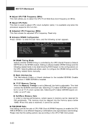
...It is available only when the processor supports this area is set to select the CPU Front Side Bus clock frequency (in memory can be cached. Disable the function if 16MB SDRAM is installed. 1T/2T Memory Timing W hen the Memory Timings is reserved, it cannot be ...makes SDRAM signal controller run at different frequency combinations (non-synchronous overclocking). Selecting [1T] makes SDRAM signal controller to be mapped into the memory space below 16MB. Setting to [Auto] enables DRAM timings and the following screen appears. Adjusted CPU Frequency (M Hz) This item shows ...
...It is available only when the processor supports this area is set to select the CPU Front Side Bus clock frequency (in memory can be cached. Disable the function if 16MB SDRAM is installed. 1T/2T Memory Timing W hen the Memory Timings is reserved, it cannot be ...makes SDRAM signal controller run at different frequency combinations (non-synchronous overclocking). Selecting [1T] makes SDRAM signal controller to be mapped into the memory space below 16MB. Setting to [Auto] enables DRAM timings and the following screen appears. Adjusted CPU Frequency (M Hz) This item shows ...


