User Guide
Page 4
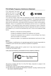
... RACCORDER AU RESEAU. power cord, if any, must accept any interference received, including interference that may cause harmful interference to radio communications. Micro-Star International MS-7374 This device complies with the limits for help. However, there is no guarantee that to which can radiate radio frequency energy and, if not installed...
... RACCORDER AU RESEAU. power cord, if any, must accept any interference received, including interference that may cause harmful interference to radio communications. Micro-Star International MS-7374 This device complies with the limits for help. However, there is no guarantee that to which can radiate radio frequency energy and, if not installed...
User Guide
Page 10
Getting Started Chapter 1 Getting Started Thank you for optimal system efficiency. Designed to fit the advanced AM D® Phenom/Athlon/ Sempron series in Socket AM2/ AM2+, the K9N2 SLI Platinum Series deliver a high performance and professional desktop platform solution. 1-1 The K9N2 SLI Platinum Series mainboards are based on NVIDIA® nForce750a SLI single chipset for choosing the K9N2 SLI Platinum Series (MS-7374 v1.X) ATX mainboard.
Getting Started Chapter 1 Getting Started Thank you for optimal system efficiency. Designed to fit the advanced AM D® Phenom/Athlon/ Sempron series in Socket AM2/ AM2+, the K9N2 SLI Platinum Series deliver a high performance and professional desktop platform solution. 1-1 The K9N2 SLI Platinum Series mainboards are based on NVIDIA® nForce750a SLI single chipset for choosing the K9N2 SLI Platinum Series (MS-7374 v1.X) ATX mainboard.
User Guide
Page 11
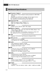
... Compliant with 360KB, 720KB, 1.2MB, 1.44MB and 2.88MB 1-2 Supports PIO, Bus Master operation mode SATA - 6 SATAII ports by nForce 750a SLI - 2 ESATA (External-SATA) ports (back panel) by VIA VT6308P (optional) Audio - Supports Ultra DMA 66/100/133 mode - Supports 1 ... Max) (For more information on compatible components, please visit ht t p: / / gl oba l. ms i . Supports storage and data transfers at up to 3 Gb/s RAID - c om. Chip integrated by Realtek 8211BL 1394 (optional) - MS-7374 Mainboard Mainboard Specifications Processor Support - php?f unc = c puf orm) Supported FSB -
... Compliant with 360KB, 720KB, 1.2MB, 1.44MB and 2.88MB 1-2 Supports PIO, Bus Master operation mode SATA - 6 SATAII ports by nForce 750a SLI - 2 ESATA (External-SATA) ports (back panel) by VIA VT6308P (optional) Audio - Supports Ultra DMA 66/100/133 mode - Supports 1 ... Max) (For more information on compatible components, please visit ht t p: / / gl oba l. ms i . Supports storage and data transfers at up to 3 Gb/s RAID - c om. Chip integrated by Realtek 8211BL 1394 (optional) - MS-7374 Mainboard Mainboard Specifications Processor Support - php?f unc = c puf orm) Supported FSB -
User Guide
Page 13
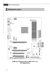
... 63 0 8P ( op ti on a l) RESET PWR_BTN B AT T + JMicron J MB 36 3 ( Optional) JTPM1 JUSB1 JUSB2 JUSB3 FDD1 JFP1 JFP2 J1394_1(Opti onal) IDE2 SYSFAN4 K9N2 SLI Platinum Series (MS-7374 v1.X) ATX Mainboard 1-4 MS-7374 Mainboard Mainboard Layout JP W 3 C PUFAN 1 Top : mouse Bo t tom: ke y b oa rd Top: DVI ports Bottom: 1394 port (optional) Optical SPDIF-out IDE...
... 63 0 8P ( op ti on a l) RESET PWR_BTN B AT T + JMicron J MB 36 3 ( Optional) JTPM1 JUSB1 JUSB2 JUSB3 FDD1 JFP1 JFP2 J1394_1(Opti onal) IDE2 SYSFAN4 K9N2 SLI Platinum Series (MS-7374 v1.X) ATX Mainboard 1-4 MS-7374 Mainboard Mainboard Layout JP W 3 C PUFAN 1 Top : mouse Bo t tom: ke y b oa rd Top: DVI ports Bottom: 1394 port (optional) Optical SPDIF-out IDE...
User Guide
Page 18
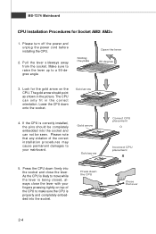
MS-7374 Mainboard CPU Installation Procedures for the gold arrow on top of the correct installation procedures may cause permanent damages to your fingers pressing tightly on ...
MS-7374 Mainboard CPU Installation Procedures for the gold arrow on top of the correct installation procedures may cause permanent damages to your fingers pressing tightly on ...
User Guide
Page 20
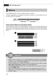
... up , always insert the memory modules into the DIM M1 first. - For more information on compatible components, please visit http://global.msi.com. DDR2 memory modules are used for Dual-Channel mode. 1 DIMM1 DIMM2 DIMM3 DIMM4 2 DIMM1 DIMM2 DIMM3 DIMM4 Installed Empty Important ...the memory modules can enhance the system performance. You should always install DDR2 memory modules in different channel DIMM slots. - MS-7374 Mainboard Memory These DIMM slots are not interchangeable with a 2GB memory module. 2-6 The following illustrations explain the population rules for installing memory...
... up , always insert the memory modules into the DIM M1 first. - For more information on compatible components, please visit http://global.msi.com. DDR2 memory modules are used for Dual-Channel mode. 1 DIMM1 DIMM2 DIMM3 DIMM4 2 DIMM1 DIMM2 DIMM3 DIMM4 Installed Empty Important ...the memory modules can enhance the system performance. You should always install DDR2 memory modules in different channel DIMM slots. - MS-7374 Mainboard Memory These DIMM slots are not interchangeable with a 2GB memory module. 2-6 The following illustrations explain the population rules for installing memory...

User Guide
Page 22
... the power supply is used to provide power to the CPU. You may use the 20-pin ATX power supply, please plug your power supply along with pin 1 & pin 13 (refer to the...5V 10 +12V 22 +5V 11 +12V 23 +5V 12 +3.3V 24 GND pin 13 pin 12 ATX 8-pin/ 4-pin Power Connector: JPW3/ JPW2 This JPW 3 power connector is inserted in the proper orientation and the... PIN SIGNAL 5 +12V 6 +12V 7 +12V 8 +12V 1 JPW2 Pin Definition PIN SIGNAL 1 5V 2 GND 3 GND 4 12V 2-8 MS-7374 Mainboard Power Supply ATX 24-Pin Power Connector: ATX1 This connector allows you like to use the 20-pin...
... the power supply is used to provide power to the CPU. You may use the 20-pin ATX power supply, please plug your power supply along with pin 1 & pin 13 (refer to the...5V 10 +12V 22 +5V 11 +12V 23 +5V 12 +3.3V 24 GND pin 13 pin 12 ATX 8-pin/ 4-pin Power Connector: JPW3/ JPW2 This JPW 3 power connector is inserted in the proper orientation and the... PIN SIGNAL 5 +12V 6 +12V 7 +12V 8 +12V 1 JPW2 Pin Definition PIN SIGNAL 1 5V 2 GND 3 GND 4 12V 2-8 MS-7374 Mainboard Power Supply ATX 24-Pin Power Connector: ATX1 This connector allows you like to use the 20-pin...
User Guide
Page 24
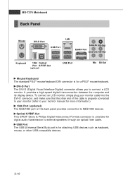
... & Philips Digital Interconnect Format) connector is provided for a PS/2® mouse/keyboard. It provides a high-speed digital interconnection between the computer and its display device. MS-7374 Mainboard Back Panel Mouse DVI-D Port LAN USB Port Line-In RS-Out ESATA Port Line-Out CS-Out Keyboard 1394 Optical Port S/PDIF-Out...
... & Philips Digital Interconnect Format) connector is provided for a PS/2® mouse/keyboard. It provides a high-speed digital interconnection between the computer and its display device. MS-7374 Mainboard Back Panel Mouse DVI-D Port LAN USB Port Line-In RS-Out ESATA Port Line-Out CS-Out Keyboard 1394 Optical Port S/PDIF-Out...
User Guide
Page 26
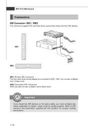
... drives separately to master / slave mode by the vendors for jumper setting instructions. 2-12 IDE2 (Secondary IDE Connector) IDE2 can connect a Master and a Slave drive. MS-7374 Mainboard Connectors IDE Connector: IDE1 / IDE2 This connector supports IDE hard disk drives, optical disk drives and other IDE devices. IDE1 IDE2 IDE1 (Primary IDE...
... drives separately to master / slave mode by the vendors for jumper setting instructions. 2-12 IDE2 (Secondary IDE Connector) IDE2 can connect a Master and a Slave drive. MS-7374 Mainboard Connectors IDE Connector: IDE1 / IDE2 This connector supports IDE hard disk drives, optical disk drives and other IDE devices. IDE1 IDE2 IDE1 (Primary IDE...
User Guide
Page 28
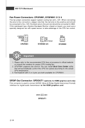
... advantage of the CPU fan control. SPDIF-Out Connector: SPDOUT1 (optional, for HDMI graphics card only) This connector is used to the actual CPU temperature. 3. MS-7374 Mainboard Fan Power Connectors: CPUFAN1, SYSFAN1/ 2/ 3/ 4 The fan power connectors support system cooling fan with +12V.
... advantage of the CPU fan control. SPDIF-Out Connector: SPDOUT1 (optional, for HDMI graphics card only) This connector is used to the actual CPU temperature. 3. MS-7374 Mainboard Fan Power Connectors: CPUFAN1, SYSFAN1/ 2/ 3/ 4 The fan power connectors support system cooling fan with +12V.

User Guide
Page 30
MS-7374 Mainboard Front USB Connector: JUSB1/ JUSB2/ JUSB3 This connector, compliant with Intel® I/O Connectivity Design Guide, is a 16550A high speed communication port that the pins ...
MS-7374 Mainboard Front USB Connector: JUSB1/ JUSB2/ JUSB3 This connector, compliant with Intel® I/O Connectivity Design Guide, is a 16550A high speed communication port that the pins ...
User Guide
Page 32
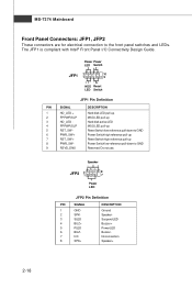
... Power Switch high reference pull-up Reset Switch high reference pull-up Power Switch low reference pull-down to the front panel switches and LEDs. MS-7374 Mainboard Front Panel Connectors: JFP1, JFP2 These connectors are for electrical connection to GND Reserved.
... Power Switch high reference pull-up Reset Switch high reference pull-up Power Switch low reference pull-down to the front panel switches and LEDs. MS-7374 Mainboard Front Panel Connectors: JFP1, JFP2 These connectors are for electrical connection to GND Reserved.
User Guide
Page 34
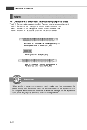
MS-7374 Mainboard Slots PCI (Peripheral Component Interconnect) Express Slots The PCI Express slot supports the PCI Express interface expansion card. Mazarine PCI Express x16 Slot supports ...
MS-7374 Mainboard Slots PCI (Peripheral Component Interconnect) Express Slots The PCI Express slot supports the PCI Express interface expansion card. Mazarine PCI Express x16 Slot supports ...
User Guide
Page 36
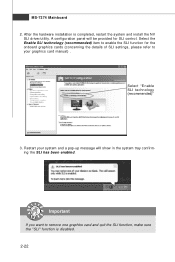
... refer to remove one graphics card and quit the SLI function, make sure the "SLI" function is completed, restart the system and install the NV SLI driver/utility. After the hardware installation is disabled. 2-22 Select the Enable SLI technology (recommended) item to enable the SLI function for SLI control. MS-7374 Mainboard 2. Restart your graphics card manual) .
... refer to remove one graphics card and quit the SLI function, make sure the "SLI" function is completed, restart the system and install the NV SLI driver/utility. After the hardware installation is disabled. 2-22 Select the Enable SLI technology (recommended) item to enable the SLI function for SLI control. MS-7374 Mainboard 2. Restart your graphics card manual) .
User Guide
Page 38
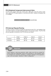
... 133 MBps. 32-bit PCI Slot PCI Interrupt Request Routing The IRQ, acronym of interrupt request line and pronounced I-R-Q, are typically connected to the microprocessor. MS-7374 Mainboard PCI (Peripheral Component Interconnect) Slots The PCI slots support LAN cards, SCSI cards, USB cards, and other add-on cards that you unplug the...
... 133 MBps. 32-bit PCI Slot PCI Interrupt Request Routing The IRQ, acronym of interrupt request line and pronounced I-R-Q, are typically connected to the microprocessor. MS-7374 Mainboard PCI (Peripheral Component Interconnect) Slots The PCI slots support LAN cards, SCSI cards, USB cards, and other add-on cards that you unplug the...
User Guide
Page 40
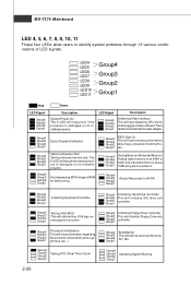
... This will start showing information about logo, processor brand name, etc... Group4 Group3 Group2 Group1 BIOS Sign On This will initialize IDE drive and controller. MS-7374 Mainboard LED 4, 5, 6, 7, 8, 9, 10, 11 These four LEDs allow users to RAM for fast booting. LED4 LED5 LED6 LED7 LED8 LED9 LED10 LED11 Group4 Group3 Group2...
... This will start showing information about logo, processor brand name, etc... Group4 Group3 Group2 Group1 BIOS Sign On This will initialize IDE drive and controller. MS-7374 Mainboard LED 4, 5, 6, 7, 8, 9, 10, 11 These four LEDs allow users to RAM for fast booting. LED4 LED5 LED6 LED7 LED8 LED9 LED10 LED11 Group4 Group3 Group2...
User Guide
Page 42
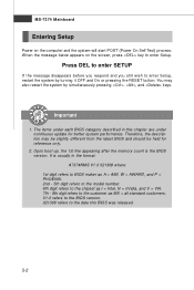
... digit refers to BIOS maker as A = AMI, W = AWARD, and P = PHOENIX. 2nd - 5th digit refers to the model number. 6th digit refers to the chipset as MS = all standard customers. Press DEL to enter SETUP If the message disappears before you respond and you still wish to enter Setup. W hen the message... below appears on the computer and the system will start POST (Power On Self Test) process. MS-7374 Mainboard Entering Setup Power on the screen, press key to enter Setup, restart the system by simultaneously pressing , , and keys.
... digit refers to BIOS maker as A = AMI, W = AWARD, and P = PHOENIX. 2nd - 5th digit refers to the model number. 6th digit refers to the chipset as MS = all standard customers. Press DEL to enter SETUP If the message disappears before you respond and you still wish to enter Setup. W hen the message... below appears on the computer and the system will start POST (Power On Self Test) process. MS-7374 Mainboard Entering Setup Power on the screen, press key to enter Setup, restart the system by simultaneously pressing , , and keys.
User Guide
Page 44
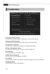
Integrated Peripherals Use this menu to specify your settings for frequency/voltage control and overclocking. MS-7374 Mainboard The Main Menu Standard CMOS Features Use this menu for BIOS. Power Management Setup Use this menu to specify your settings for power management. ...
Integrated Peripherals Use this menu to specify your settings for frequency/voltage control and overclocking. MS-7374 Mainboard The Main Menu Standard CMOS Features Use this menu for BIOS. Power Management Setup Use this menu to specify your settings for power management. ...
User Guide
Page 46
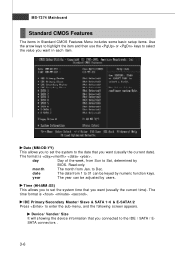
MS-7374 Mainboard Standard CMOS Features The items in each item. month The month from 1 to enter the sub-menu, and the following screen appears. Time (HH:...
MS-7374 Mainboard Standard CMOS Features The items in each item. month The month from 1 to enter the sub-menu, and the following screen appears. Time (HH:...
User Guide
Page 48
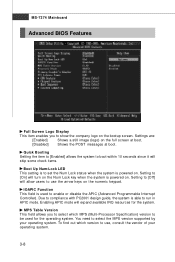
... full screen at boot. [Disabled] Shows the POST messages at boot. Due to compliance with PC2001 design guide, the system is used for the system. MS-7374 Mainboard Advanced BIOS Features Full Screen Logo Display This item enables you to select which version to use the arrow keys on the numeric keypad.
... full screen at boot. [Disabled] Shows the POST messages at boot. Due to compliance with PC2001 design guide, the system is used for the system. MS-7374 Mainboard Advanced BIOS Features Full Screen Logo Display This item enables you to select which version to use the arrow keys on the numeric keypad.


