User Guide
Page 2
... First release for PCB 1.X Date April 2008 Technical Support If a problem arises with your place of purchase or local distributor. Our products are registered trademarks of AMD Corporation. Award® is a registered trademark of Novell, Inc. Alternatively, please try the following help resources for FAQ, technical guide, BIOS updates, driver updates, and other countries. W indows® 95/98/2000...
... First release for PCB 1.X Date April 2008 Technical Support If a problem arises with your place of purchase or local distributor. Our products are registered trademarks of AMD Corporation. Award® is a registered trademark of Novell, Inc. Alternatively, please try the following help resources for FAQ, technical guide, BIOS updates, driver updates, and other countries. W indows® 95/98/2000...
User Guide
Page 8
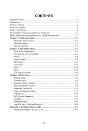
... Mainboard Layout 1-4 Packing Checklist 1-5 Chapter 2. CONTENTS Copyright Notice ...ii Trademarks ...ii Revision History ...ii Technical Support ...ii Safety Instructions ...iii FCC-B Radio Frequency Interference Statement iv W EEE (Waste Electrical and Electronic Equipment) Statement v Chapter 1. Hardware Setup 2-1 Quick Components Guide 2-2 CPU (Central Processing Unit 2-3 Memory ...2-6 Power Supply ...2-8 Back Panel ...2-10 Connectors ...2-12 Button ...2-19 Slots ...2-20 LED Status Indicators 2-25 Chapter 3 BIOS Setup 3-1 Entering Setup ...3-2 The Main Menu ...3-4 Standard CMOS...
... Mainboard Layout 1-4 Packing Checklist 1-5 Chapter 2. CONTENTS Copyright Notice ...ii Trademarks ...ii Revision History ...ii Technical Support ...ii Safety Instructions ...iii FCC-B Radio Frequency Interference Statement iv W EEE (Waste Electrical and Electronic Equipment) Statement v Chapter 1. Hardware Setup 2-1 Quick Components Guide 2-2 CPU (Central Processing Unit 2-3 Memory ...2-6 Power Supply ...2-8 Back Panel ...2-10 Connectors ...2-12 Button ...2-19 Slots ...2-20 LED Status Indicators 2-25 Chapter 3 BIOS Setup 3-1 Entering Setup ...3-2 The Main Menu ...3-4 Standard CMOS...
User Guide
Page 11
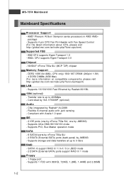
... visit ht t p: / / g loba l. Chip integrated by VIA VT6308P (optional) Audio - Supports PIO, Bus Master operation mode SATA - 6 SATAII ports by nForce 750a SLI - 2 ESATA (External-SATA) ports (back panel) by Realtek 8211BL 1394 (optional) - AM2 CPU supports Hyper Transport 1.0 - c om. Supports storage and data transfers at up to 3 Gb/s RAID - MS-7374 Mainboard Mainboard Specifications Processor Support - NVIDIA® nForce 750a SLI (MCP 72P) chipset Memory Support - Transfer rate is up to 400Mbps - t w / i ndex . Supports 4 pin CPU Fan Pin-Header with 360KB, 720KB...
... visit ht t p: / / g loba l. Chip integrated by VIA VT6308P (optional) Audio - Supports PIO, Bus Master operation mode SATA - 6 SATAII ports by nForce 750a SLI - 2 ESATA (External-SATA) ports (back panel) by Realtek 8211BL 1394 (optional) - AM2 CPU supports Hyper Transport 1.0 - c om. Supports storage and data transfers at up to 3 Gb/s RAID - MS-7374 Mainboard Mainboard Specifications Processor Support - NVIDIA® nForce 750a SLI (MCP 72P) chipset Memory Support - Transfer rate is up to 400Mbps - t w / i ndex . Supports 4 pin CPU Fan Pin-Header with 360KB, 720KB...
User Guide
Page 12
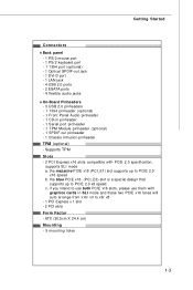
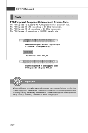
... Panel Audio pinheader - 1 CD-in SLI mode and these two PCIE x16 lanes will auto arrange from x16/ x0 to x8/ x8 - 1 PCI Express x 1 slot - 2 PCI slots Form Factor - ATX (30.5cm X 24.4 cm) Mounting - 9 mounting holes 1-3 if you intend to use both PCIE x16 slots, please use them with PCIE 2.0 specification, supports SLI mode a. the blue PCIE x16 (PCI_E3) slot is a special design that supports up to PCIE 2.0 x8 speed c. Supports TPM Slots - 2 PCI Express x16 slots compatible with graphics cards in pinheader - 1 Serial port...
... Panel Audio pinheader - 1 CD-in SLI mode and these two PCIE x16 lanes will auto arrange from x16/ x0 to x8/ x8 - 1 PCI Express x 1 slot - 2 PCI slots Form Factor - ATX (30.5cm X 24.4 cm) Mounting - 9 mounting holes 1-3 if you intend to use both PCIE x16 slots, please use them with PCIE 2.0 specification, supports SLI mode a. the blue PCIE x16 (PCI_E3) slot is a special design that supports up to PCIE 2.0 x8 speed c. Supports TPM Slots - 2 PCI Express x16 slots compatible with graphics cards in pinheader - 1 Serial port...
User Guide
Page 24
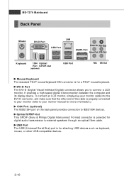
... its display device. Optical S/PDIF-Out This SPDIF (Sony & Philips Digital Interconnect Format) connector is properly connected to your monitor (refer to your monitor cable into the DVI-D connector, and make sure that the other USB-compatible devices. 2-10 USB Port The USB (Universal Serial Bus) port is for a PS/2® mouse/keyboard. DVI-D Port The DVI-D (Digital Visual Interface-Digital) connector allows you to connect a LCD monitor. MS-7374 Mainboard Back Panel Mouse DVI-D Port LAN USB Port...
... its display device. Optical S/PDIF-Out This SPDIF (Sony & Philips Digital Interconnect Format) connector is properly connected to your monitor (refer to your monitor cable into the DVI-D connector, and make sure that the other USB-compatible devices. 2-10 USB Port The USB (Universal Serial Bus) port is for a PS/2® mouse/keyboard. DVI-D Port The DVI-D (Digital Visual Interface-Digital) connector allows you to connect a LCD monitor. MS-7374 Mainboard Back Panel Mouse DVI-D Port LAN USB Port...
User Guide
Page 26
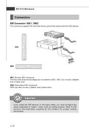
... and a Slave drive. Refer to IDE device's documentation supplied by setting jumpers. IDE2 (Secondary IDE Connector) IDE2 can connect a Master and a Slave drive. MS-7374 Mainboard Connectors IDE Connector: IDE1 / IDE2 This connector supports IDE hard disk drives, optical disk drives and other IDE devices. IDE1 IDE2 IDE1 (Primary IDE Connector) The first hard drive should always be connected to master / slave mode by the vendors for jumper setting instructions. 2-12 Important If you install two IDE devices on the same cable, you must configure the drives separately to...
... and a Slave drive. Refer to IDE device's documentation supplied by setting jumpers. IDE2 (Secondary IDE Connector) IDE2 can connect a Master and a Slave drive. MS-7374 Mainboard Connectors IDE Connector: IDE1 / IDE2 This connector supports IDE hard disk drives, optical disk drives and other IDE devices. IDE1 IDE2 IDE1 (Primary IDE Connector) The first hard drive should always be connected to master / slave mode by the vendors for jumper setting instructions. 2-12 Important If you install two IDE devices on the same cable, you must configure the drives separately to...
User Guide
Page 28
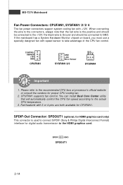
... or Sensor SYSFAN1/2/3 SYSFAN4 Important 1. CPUFAN1 supports fan control. the black wire is used to connect S/PDIF (Sony & Philips Digital Interconnect Format) interface for proper CPU cooling fan. 2. SPDIF GND SPDOUT1 2-14 SPDIF-Out Connector: SPDOUT1 (optional, for HDMI graphics card only) This connector is Ground and should be connected to the actual CPU temperature. 3. If the mainboard has a System Hardware Monitor chipset on-board, you must use a specially designed fan with speed sensor to the HDMI graphics card.
... or Sensor SYSFAN1/2/3 SYSFAN4 Important 1. CPUFAN1 supports fan control. the black wire is used to connect S/PDIF (Sony & Philips Digital Interconnect Format) interface for proper CPU cooling fan. 2. SPDIF GND SPDOUT1 2-14 SPDIF-Out Connector: SPDOUT1 (optional, for HDMI graphics card only) This connector is Ground and should be connected to the actual CPU temperature. 3. If the mainboard has a System Hardware Monitor chipset on-board, you must use a specially designed fan with speed sensor to the HDMI graphics card.
User Guide
Page 34
... PCI Express x 16 Slot supports up to 4.0 GB/s transfer rate. MS-7374 Mainboard Slots PCI (Peripheral Component Interconnect) Express Slots The PCI Express slot supports the PCI Express interface expansion card. Meanwhile, read the documentation for the expansion card, such as jumpers, switches or BIOS configuration. 2-20 The PCI Express 2.0 x 16 supports up to configure any necessary hardware or software settings for the expansion card to PCI Express 2.0 x 8 speed (PCI_E3) Important When adding or removing expansion cards, make sure that you unplug the power supply...
... PCI Express x 16 Slot supports up to 4.0 GB/s transfer rate. MS-7374 Mainboard Slots PCI (Peripheral Component Interconnect) Express Slots The PCI Express slot supports the PCI Express interface expansion card. Meanwhile, read the documentation for the expansion card, such as jumpers, switches or BIOS configuration. 2-20 The PCI Express 2.0 x 16 supports up to configure any necessary hardware or software settings for the expansion card to PCI Express 2.0 x 8 speed (PCI_E3) Important When adding or removing expansion cards, make sure that you unplug the power supply...
User Guide
Page 35
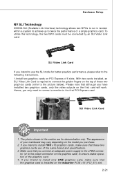
... graphics card. 4. SLI Video Link Card If you intend to install only ONE graphics card, make sure that you purchase. 2. W ith two cards installed, an SLI Video Link Card is Installed on PCI Express x16 slots. If you intend to install TWO x16 graphics cards, make sure that although you only need to connect a monitor to twice the performance of the same brand and specifications. 3. To utilize this section are of a single graphics card. Hardware Setup NV SLI Technology...
... graphics card. 4. SLI Video Link Card If you intend to install only ONE graphics card, make sure that you purchase. 2. W ith two cards installed, an SLI Video Link Card is Installed on PCI Express x16 slots. If you intend to install TWO x16 graphics cards, make sure that although you only need to connect a monitor to twice the performance of the same brand and specifications. 3. To utilize this section are of a single graphics card. Hardware Setup NV SLI Technology...
User Guide
Page 37
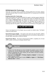
... "VGA Share Memory Size" in the system tray. Important 1. The Hybrid modes are simultaneously active and working collaboratively to show in BIOS. 2-23 The hybrid mode where the discrete GPU (dGPU) and mainboard GPU (mGPU) are listed below. The hybrid mode where the dGPU completely shut off the system and install the NVIDIA SLI graphic card that you have installed the graphics card in the PCI Express slot, only the onboard video...
... "VGA Share Memory Size" in the system tray. Important 1. The Hybrid modes are simultaneously active and working collaboratively to show in BIOS. 2-23 The hybrid mode where the discrete GPU (dGPU) and mainboard GPU (mGPU) are listed below. The hybrid mode where the dGPU completely shut off the system and install the NVIDIA SLI graphic card that you have installed the graphics card in the PCI Express slot, only the onboard video...
User Guide
Page 38
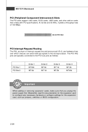
... to the PCI bus pins as jumpers, switches or BIOS configuration. 2-24 MS-7374 Mainboard PCI (Peripheral Component Interconnect) Slots The PCI slots support LAN cards, SCSI cards, USB cards, and other add-on cards that you unplug the power supply first. At 32 bits and 33 MHz, it yields a throughput rate of 133 MBps. 32-bit PCI Slot PCI Interrupt Request Routing The IRQ, acronym of interrupt request line and pronounced I-R-Q, are typically connected to the...
... to the PCI bus pins as jumpers, switches or BIOS configuration. 2-24 MS-7374 Mainboard PCI (Peripheral Component Interconnect) Slots The PCI slots support LAN cards, SCSI cards, USB cards, and other add-on cards that you unplug the power supply first. At 32 bits and 33 MHz, it yields a throughput rate of 133 MBps. 32-bit PCI Slot PCI Interrupt Request Routing The IRQ, acronym of interrupt request line and pronounced I-R-Q, are typically connected to the...
User Guide
Page 47
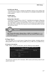
... the device supports it and the devices is a utility that is going to fail to a safe place before the hard disk becomes offline. System Information Press to enable or disable the LBA Mode. This sub-menu shows the CPU information, BIOS version and memory status of floppy drives installed. S.M.A.R.T. Important IDE Primary/Secondary M aster/Slave, SATA1~6 & E-SATA1/2 are appearing when you to set the type of your disk status to predict hard disk failure. Available options...
... the device supports it and the devices is a utility that is going to fail to a safe place before the hard disk becomes offline. System Information Press to enable or disable the LBA Mode. This sub-menu shows the CPU information, BIOS version and memory status of floppy drives installed. S.M.A.R.T. Important IDE Primary/Secondary M aster/Slave, SATA1~6 & E-SATA1/2 are appearing when you to set the type of your disk status to predict hard disk failure. Available options...
User Guide
Page 49
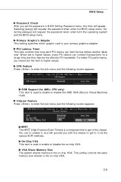
... BIOS Setting Password menu, this item will provide you should set to higher values, every PCI device can conduct transactions for AM2+ CPU only) This item is used to enable or disable the AMD SVM (Secure Virtual Machine) mode. Selecting [setup] will request the password when enter both the operating system and the BIOS setup menu. Selecting [always] will request the password when enter the BIOS setup menu. This setting controls the exact memory size shared to the on -chip VGA...
... BIOS Setting Password menu, this item will provide you should set to higher values, every PCI device can conduct transactions for AM2+ CPU only) This item is used to enable or disable the AMD SVM (Secure Virtual Machine) mode. Selecting [setup] will request the password when enter both the operating system and the BIOS setup menu. Selecting [always] will request the password when enter the BIOS setup menu. This setting controls the exact memory size shared to the on -chip VGA...
User Guide
Page 51
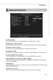
... onboard HD audio controller. 3-11 Onboard LAN Controller This item is used to invoke the Boot ROM of the LAN controller. RAID Mode This item allows you to use a USB-interfaced device in the operating system. Select [RAID] will enable RAID. Extra RAID/IDE Controller (for extra RAID/ IDE controller. HD Audio Controller This item allows you to enable/disable the extra RAID/IDE JMB363 controller (IDE2, ESATA1 and E-SATA2). LAN Option ROM This item is used to decide whether to enable/disable the onboard LAN controller. Integrated Peripherals BIOS Setup USB Controller This setting...
... onboard HD audio controller. 3-11 Onboard LAN Controller This item is used to invoke the Boot ROM of the LAN controller. RAID Mode This item allows you to use a USB-interfaced device in the operating system. Select [RAID] will enable RAID. Extra RAID/IDE Controller (for extra RAID/ IDE controller. HD Audio Controller This item allows you to enable/disable the extra RAID/IDE JMB363 controller (IDE2, ESATA1 and E-SATA2). LAN Option ROM This item is used to decide whether to enable/disable the onboard LAN controller. Integrated Peripherals BIOS Setup USB Controller This setting...
User Guide
Page 56
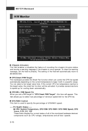
... Speed, CPU Vcore, 3.3V, 5V, 12V These items display the current status of all of SYSFAN1 speed. ---- To clear the warning message, set a FAN target in a specific range. The setting of recording the chassis intrusion status and issuing a warning message if the chassis is used to specify the percentage of the monitored hardware devices/ components such as CPU voltage, temperatures and all fans' speeds. 3-16 CPU Smart FAN Target The mainboard provides the Smart Fan...
... Speed, CPU Vcore, 3.3V, 5V, 12V These items display the current status of all of SYSFAN1 speed. ---- To clear the warning message, set a FAN target in a specific range. The setting of recording the chassis intrusion status and issuing a warning message if the chassis is used to specify the percentage of the monitored hardware devices/ components such as CPU voltage, temperatures and all fans' speeds. 3-16 CPU Smart FAN Target The mainboard provides the Smart Fan...
User Guide
Page 61
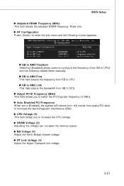
... CPU) and the following screen appears. Read only. Auto Disabled PCI Frequency W hen set to [Enabled], the system will remove (turn off) clocks from SB to select the PCI Express frequency (in MHz). Adjust PCI-E Frequency (MHz) This field allows you to enter the sub-menu and the following related items manually. DRAM Voltage (V) Adjusting the voltage can increase the memory speed. NB Voltage (V) Adjust the North Bridge chipset voltage. HT Configuration Press to increase the CPU voltage. HT Link Voltage...
... CPU) and the following screen appears. Read only. Auto Disabled PCI Frequency W hen set to [Enabled], the system will remove (turn off) clocks from SB to select the PCI Express frequency (in MHz). Adjust PCI-E Frequency (MHz) This field allows you to enter the sub-menu and the following related items manually. DRAM Voltage (V) Adjusting the voltage can increase the memory speed. NB Voltage (V) Adjust the North Bridge chipset voltage. HT Configuration Press to increase the CPU voltage. HT Link Voltage...
User Guide
Page 89
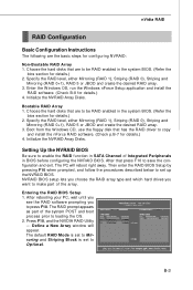
... window will reboot right away. Choose the hard disks that are to be RAID enabled in the system BIOS. (Refer the bios section for details.) 2. Setting Up the NVRAID BIOS Be sure to enable the RAID function in SATA Channel of the system POST and boot process prior to loading the OS. 2. NVRAID BIOS setup lets you choose the RAID array type and which hard drives you to press F10. The default RAID Mode is set...
... window will reboot right away. Choose the hard disks that are to be RAID enabled in the system BIOS. (Refer the bios section for details.) 2. Setting Up the NVRAID BIOS Be sure to enable the RAID function in SATA Channel of the system POST and boot process prior to loading the OS. 2. NVRAID BIOS setup lets you choose the RAID array type and which hard drives you to press F10. The default RAID Mode is set...
User Guide
Page 93
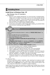
... bits) or WinVista64 (for NVIDIA RAID Controller is not the case, then press F6 when prompted at the Specify Devices screen, then press ENTER. 7. W hen you start installing W indows XP, you install the RAID management tool. b. You should be shown a list of W indows XP installation is recommended that hard drive. Please refer the Important notice above to insert a floppy disk containing the NVIDIA RAID driver into the CD-ROM drive. The driver...
... bits) or WinVista64 (for NVIDIA RAID Controller is not the case, then press F6 when prompted at the Specify Devices screen, then press ENTER. 7. W hen you start installing W indows XP, you install the RAID management tool. b. You should be shown a list of W indows XP installation is recommended that hard drive. Please refer the Important notice above to insert a floppy disk containing the NVIDIA RAID driver into the CD-ROM drive. The driver...
User Guide
Page 113
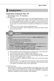
... the type of one or more mass storage devices installed in step 3 and press Enter. 5. Insert the MSI CD into the A: drive. You have selected the JMicron RAID controller. C-11 Press the "S" key to continue. 8. Press ENTER again to select "Specify Additional Device". 3. For W indows Vista: After selecting the location to install W indows Vista, please click on the Setup screen. 3. Click the "Browse CD" on the "Load Driver" button...
... the type of one or more mass storage devices installed in step 3 and press Enter. 5. Insert the MSI CD into the A: drive. You have selected the JMicron RAID controller. C-11 Press the "S" key to continue. 8. Press ENTER again to select "Specify Additional Device". 3. For W indows Vista: After selecting the location to install W indows Vista, please click on the Setup screen. 3. Click the "Browse CD" on the "Load Driver" button...
User Guide
Page 123
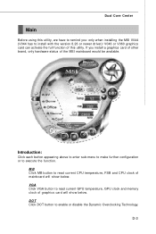
... to install with the version 8.26 or newer driver)/ V046 or V060 graphics card can activate the full function of the MSI mainboard would be available. D-3 MB Click MB button to read current GPU temperature, GPU clock and memory clock of mainboard will show below . Introduction: Click each button appearing above to enter sub-menu to make further configuration or to enable or disable the Dynamic Overclocking Technology. DOT Click DOT button...
... to install with the version 8.26 or newer driver)/ V046 or V060 graphics card can activate the full function of the MSI mainboard would be available. D-3 MB Click MB button to read current GPU temperature, GPU clock and memory clock of mainboard will show below . Introduction: Click each button appearing above to enter sub-menu to make further configuration or to enable or disable the Dynamic Overclocking Technology. DOT Click DOT button...


