User Guide
Page 8
Hardware Setup 2-1 Quick Components Guide 2-2 CPU (Central Processing Unit 2-3 Memory ...2-6 Power Supply ...2-8 Back Panel ...2-10 Connectors ...2-12 Button ...2-19 Slots ...2-20 LED Status Indicators 2-25 Chapter 3 BIOS Setup 3-1 Entering Setup ...3-2 The Main Menu ...3-4 Standard CMOS Features 3-6 Advanced BIOS Features 3-8 Integrated Peripherals 3-11 Power Management Setup 3-13 H/W Monitor ...3-...
Hardware Setup 2-1 Quick Components Guide 2-2 CPU (Central Processing Unit 2-3 Memory ...2-6 Power Supply ...2-8 Back Panel ...2-10 Connectors ...2-12 Button ...2-19 Slots ...2-20 LED Status Indicators 2-25 Chapter 3 BIOS Setup 3-1 Entering Setup ...3-2 The Main Menu ...3-4 Standard CMOS Features 3-6 Advanced BIOS Features 3-8 Integrated Peripherals 3-11 Power Management Setup 3-13 H/W Monitor ...3-...
User Guide
Page 25
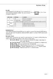
... another computer on the LAN. RS-Out (Black) - Audio Ports These audio connectors are used for microphones. Line-Out (Green) - SS-Out (Gray) - Green / Orange LED Color Left Orange Green Right Orange LED State condition Off LAN link is a connector for audio devices.
... another computer on the LAN. RS-Out (Black) - Audio Ports These audio connectors are used for microphones. Line-Out (Green) - SS-Out (Gray) - Green / Orange LED Color Left Orange Green Right Orange LED State condition Off LAN link is a connector for audio devices.
User Guide
Page 32
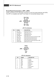
... Do not use. MS-7374 Mainboard Front Panel Connectors: JFP1, JFP2 These connectors are for electrical connection to GND Reserved. Power Power LED Switch - + JFP1 2 1 10 9 + - - + HDD Reset LED Switch JFP1 Pin Definition PIN SIGNAL 1 HD_LED + 2 FP PW R/SLP 3 HD_LED - 4 FP PW R/SLP 5 RST_SW - ...6 PW R_SW + 7 RST_SW + 8 PW R_SW - 9 RSVD_DNU DESCRIPTION Hard disk LED pull-up MSG LED pull-up Hard disk active LED MSG LED pull-up Reset Switch low reference pull-down to GND Power Switch high reference pull-up Reset Switch high reference pull...
... Do not use. MS-7374 Mainboard Front Panel Connectors: JFP1, JFP2 These connectors are for electrical connection to GND Reserved. Power Power LED Switch - + JFP1 2 1 10 9 + - - + HDD Reset LED Switch JFP1 Pin Definition PIN SIGNAL 1 HD_LED + 2 FP PW R/SLP 3 HD_LED - 4 FP PW R/SLP 5 RST_SW - ...6 PW R_SW + 7 RST_SW + 8 PW R_SW - 9 RSVD_DNU DESCRIPTION Hard disk LED pull-up MSG LED pull-up Hard disk active LED MSG LED pull-up Reset Switch low reference pull-down to GND Power Switch high reference pull-up Reset Switch high reference pull...
User Guide
Page 39
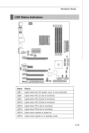
LED12 Lights when PCI_E3 slot is functional. LED14 Lights when PCI2 slot is functional. LED2 Lights when PCI_E1 slot is functional. LED15 Lights when system is on . LED16 Lights when system is power-on standby mode. 2-25 LED3 Lights when PCI_E2 slot is functional. LED13 Lights when PCI1 slot is not connected. is functional. LED Status Indicators Hardware Setup LED4 LED5 LED6 LED7 LED8 LED9 LED10 LED11 LED1 LED2 LED3 LED12 LED13 LED14 LED15 LED16 Name Status LED1 Lights when the 12V power conn.
LED12 Lights when PCI_E3 slot is functional. LED14 Lights when PCI2 slot is functional. LED2 Lights when PCI_E1 slot is functional. LED15 Lights when system is on . LED16 Lights when system is power-on standby mode. 2-25 LED3 Lights when PCI_E2 slot is functional. LED13 Lights when PCI1 slot is not connected. is functional. LED Status Indicators Hardware Setup LED4 LED5 LED6 LED7 LED8 LED9 LED10 LED11 LED1 LED2 LED3 LED12 LED13 LED14 LED15 LED16 Name Status LED1 Lights when the 12V power conn.
User Guide
Page 40
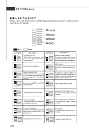
... Group4 Group3 Group2 Group1 Early Chipset Initialization Group4 Group3 Group2 Group1 Memory Detection Test Testing onboard memory size. The D-LED will start showing information about logo, processor brand name, etc... Group4 Group3 Group2 Group1 BootAttempt This will initialize Floppy... Drive and Group2 Group1 controller. MS-7374 Mainboard LED 4, 5, 6, 7, 8, 9, 10, 11 These four LEDs allow users to the screen. Group4 Group3 Group2 Group1 Testing VGA BIOS This will start detecting CPU clock...
... Group4 Group3 Group2 Group1 Early Chipset Initialization Group4 Group3 Group2 Group1 Memory Detection Test Testing onboard memory size. The D-LED will start showing information about logo, processor brand name, etc... Group4 Group3 Group2 Group1 BootAttempt This will initialize Floppy... Drive and Group2 Group1 controller. MS-7374 Mainboard LED 4, 5, 6, 7, 8, 9, 10, 11 These four LEDs allow users to the screen. Group4 Group3 Group2 Group1 Testing VGA BIOS This will start detecting CPU clock...
User Guide
Page 48
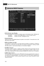
... will allow users to enable or disable the APIC (Advanced Programmable Interrupt Controller). Setting to [Off] will skip some check items. Boot Up Num-Lock LED This setting is to set the Num Lock status when the system is used for the system. To find out which MPS (Multi-Processor Specification...
... will allow users to enable or disable the APIC (Advanced Programmable Interrupt Controller). Setting to [Off] will skip some check items. Boot Up Num-Lock LED This setting is to set the Num Lock status when the system is used for the system. To find out which MPS (Multi-Processor Specification...


