User Guide
Page 8
... Interference Statement iv W EEE (Waste Electrical and Electronic Equipment) Statement v Chapter 1. Getting Started 1-1 Mainboard Specifications 1-2 Mainboard Layout 1-4 Packing Checklist 1-5 Chapter 2. Hardware Setup 2-1 Quick Components Guide 2-2 CPU (Central Processing Unit 2-3 Memory ...2-6 Power Supply ...2-8 Back Panel ...2-10 Connectors ...2-12 Button ...2-19 Slots ...2-20 LED Status Indicators 2-25 Chapter 3 BIOS Setup 3-1 Entering Setup ...3-2 The...
... Interference Statement iv W EEE (Waste Electrical and Electronic Equipment) Statement v Chapter 1. Getting Started 1-1 Mainboard Specifications 1-2 Mainboard Layout 1-4 Packing Checklist 1-5 Chapter 2. Hardware Setup 2-1 Quick Components Guide 2-2 CPU (Central Processing Unit 2-3 Memory ...2-6 Power Supply ...2-8 Back Panel ...2-10 Connectors ...2-12 Button ...2-19 Slots ...2-20 LED Status Indicators 2-25 Chapter 3 BIOS Setup 3-1 Entering Setup ...3-2 The...
User Guide
Page 11
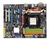
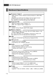
...88MB 1-2 Supports 1 FDD with jack sensing - Supports 4 pin CPU Fan Pin-Header with Azalia 1.0 spec IDE - 2 IDE ports (one by nForce 750a SLI, one by Realtek 8211BL 1394 (optional) - AM2 CPU supports Hyper Transport 1.0 - DDR2 1066 (for AM2+ CPU only)/ 800/ 667 DRAM (240pin/ 1.8V) - 4 DDR2... to 3 Gb/s RAID - AMD® Phenom/ Athlon/ Sempron series processors in AM2/ AM2+ package - c om. NVIDIA® nForce 750a SLI (MCP 72P) chipset Memory Support - Controlled by Realtek® ALC888 - Supports Ultra DMA 66/100/133 mode - MS-7374 Mainboard Mainboard Specifications Processor...
...88MB 1-2 Supports 1 FDD with jack sensing - Supports 4 pin CPU Fan Pin-Header with Azalia 1.0 spec IDE - 2 IDE ports (one by nForce 750a SLI, one by Realtek 8211BL 1394 (optional) - AM2 CPU supports Hyper Transport 1.0 - DDR2 1066 (for AM2+ CPU only)/ 800/ 667 DRAM (240pin/ 1.8V) - 4 DDR2... to 3 Gb/s RAID - AMD® Phenom/ Athlon/ Sempron series processors in AM2/ AM2+ package - c om. NVIDIA® nForce 750a SLI (MCP 72P) chipset Memory Support - Controlled by Realtek® ALC888 - Supports Ultra DMA 66/100/133 mode - MS-7374 Mainboard Mainboard Specifications Processor...
User Guide
Page 17
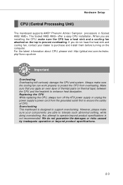
... the latest information about CPU, please visit http://global.msi.com.tw/index. However, please make sure your dealer to purchase and install them before turning on the top to support overclocking. Make sure that you apply an even layer of CPU. Overclocking This mainboard is...prevent overheating. If you are able to enhance heat dissipation. Replacing the CPU While replacing the CPU, always turn off the ATX power supply or unplug the power supply's power cord from overheating. Hardware Setup CPU (Central Processing Unit) The mainboard supports AMD® Phenom/ Athlon/ ...
... the latest information about CPU, please visit http://global.msi.com.tw/index. However, please make sure your dealer to purchase and install them before turning on the top to support overclocking. Make sure that you apply an even layer of CPU. Overclocking This mainboard is...prevent overheating. If you are able to enhance heat dissipation. Replacing the CPU While replacing the CPU, always turn off the ATX power supply or unplug the power supply's power cord from overheating. Hardware Setup CPU (Central Processing Unit) The mainboard supports AMD® Phenom/ Athlon/ ...
User Guide
Page 18
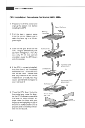
... the pins should point as shown in the correct orientation. Press down onto the socket. Gold arrow Gold arrow Correct CPU placement O Incorrect CPU placement 5. Press the CPU down firmly into the socket and can only fit in the picture. Pull the lever sideways away from the socket. ...Sliding the plate Open the lever 90 degree 3. Lower the CPU down the CPU Close the lever 2-4 If the CPU is being closed, always close the lever. Please note that any violation of the correct installation procedures may cause ...
... the pins should point as shown in the correct orientation. Press down onto the socket. Gold arrow Gold arrow Correct CPU placement O Incorrect CPU placement 5. Press the CPU down firmly into the socket and can only fit in the picture. Pull the lever sideways away from the socket. ...Sliding the plate Open the lever 90 degree 3. Lower the CPU down the CPU Close the lever 2-4 If the CPU is being closed, always close the lever. Please note that any violation of the correct installation procedures may cause ...
User Guide
Page 19
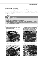
... a heat sink and a cooling fan attached on the model you purchase. 1. Hook one end of the clip to the CPU fan connector on the mainboard. 2-5 Fixed Lever 3. Mainboard photos shown in BIOS (Chapter 3). 2. Locate the Fix Lever and lift it up. Then press down...the top to prevent overheating. Position the cooling set on the computer. Hardware Setup Installing CPU Cooler Set W hen you are for demonstration of the CPU/ cooler installation only. The appearance of the retention mechanism. Attach the CPU fan cable to hook first. 2. Fasten down the other end of the clip to...
... a heat sink and a cooling fan attached on the model you purchase. 1. Hook one end of the clip to the CPU fan connector on the mainboard. 2-5 Fixed Lever 3. Mainboard photos shown in BIOS (Chapter 3). 2. Locate the Fix Lever and lift it up. Then press down...the top to prevent overheating. Position the cooling set on the computer. Hardware Setup Installing CPU Cooler Set W hen you are for demonstration of the CPU/ cooler installation only. The appearance of the retention mechanism. Attach the CPU fan cable to hook first. 2. Fasten down the other end of the clip to...

User Guide
Page 22
... supply is also a foolproof design on pin 11, 12, 23 & 24 to the CPU. You may use the 20-pin ATX power supply, please plug your power supply along with pin 1 & pin 13 (refer to connect an ATX 24-pin power supply. There is inserted in the proper orientation and the pins... 5 JPW3 4 1 PIN SIGNAL 1 GND 2 GND 3 GND 4 GND PIN SIGNAL 5 +12V 6 +12V 7 +12V 8 +12V 1 JPW2 Pin Definition PIN SIGNAL 1 5V 2 GND 3 GND 4 12V 2-8 To connect the ATX 24-pin power supply, make sure the plug of graphics card. Then push down the power supply firmly into the connector. MS-7374 Mainboard Power...
... supply is also a foolproof design on pin 11, 12, 23 & 24 to the CPU. You may use the 20-pin ATX power supply, please plug your power supply along with pin 1 & pin 13 (refer to connect an ATX 24-pin power supply. There is inserted in the proper orientation and the pins... 5 JPW3 4 1 PIN SIGNAL 1 GND 2 GND 3 GND 4 GND PIN SIGNAL 5 +12V 6 +12V 7 +12V 8 +12V 1 JPW2 Pin Definition PIN SIGNAL 1 5V 2 GND 3 GND 4 12V 2-8 To connect the ATX 24-pin power supply, make sure the plug of graphics card. Then push down the power supply firmly into the connector. MS-7374 Mainboard Power...
User Guide
Page 28
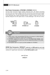
... GND. If the mainboard has a System Hardware Monitor chipset on-board, you must use a specially designed fan with +12V. Please refer to the recommended CPU fans at processor's official website or consult the vendors for CPUFAN1. Fan/heatsink with 3 or 4 pins are both available for proper... CPU cooling fan. 2. GND +12V NC CONTROL SENSOR +12V GND CPUFAN1 GND +12V NC or Sensor SYSFAN1/2/3 SYSFAN4 Important 1. CPUFAN1 supports fan control. SPDIF GND ...
... GND. If the mainboard has a System Hardware Monitor chipset on-board, you must use a specially designed fan with +12V. Please refer to the recommended CPU fans at processor's official website or consult the vendors for CPUFAN1. Fan/heatsink with 3 or 4 pins are both available for proper... CPU cooling fan. 2. GND +12V NC CONTROL SENSOR +12V GND CPUFAN1 GND +12V NC or Sensor SYSFAN1/2/3 SYSFAN4 Important 1. CPUFAN1 supports fan control. SPDIF GND ...
User Guide
Page 40
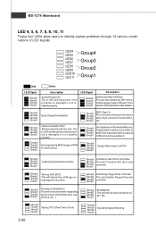
..., system bus, etc...) Group4 Group3 Group2 Group1 Testing RTC (Real Time Clock) 2-26 Group4 Group3 Group2 Group1 Initializing Hard Drive Controller This will start detecting CPU clock, checking type ofvideo onboard. Group4 Group3 Group2 Group1 Decompressing BIOS image to identify system problems through 16 various combinations of LED signals. The D-LED...
..., system bus, etc...) Group4 Group3 Group2 Group1 Testing RTC (Real Time Clock) 2-26 Group4 Group3 Group2 Group1 Initializing Hard Drive Controller This will start detecting CPU clock, checking type ofvideo onboard. Group4 Group3 Group2 Group1 Decompressing BIOS image to identify system problems through 16 various combinations of LED signals. The D-LED...
User Guide
Page 47
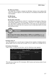
This sub-menu shows the CPU information, BIOS version and memory status of floppy drives installed. System Information Press to activate the S.M.A.R.T. (Self-Monitoring Analysis & Reporting Technology) capability for the hard ...
This sub-menu shows the CPU information, BIOS version and memory status of floppy drives installed. System Information Press to activate the S.M.A.R.T. (Self-Monitoring Analysis & Reporting Technology) capability for the hard ...
User Guide
Page 49
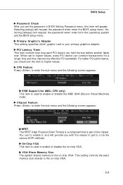
... item is part of the chipset. Primary Graphic's Adapter This setting specifies which graphic card is used to enable or disable the on -chip VGA. 3-9 CPU Feature Press to enter the sub-menu and the following screen appears: HPET The HPET (High Precision Event Timers) is a component that is used to... size shared to the on -chip VGA. For better PCI performance, you should set to higher values, every PCI device can conduct transactions for AM2+ CPU only) This item is your primary graphics adapter. VGA Share Memory Size The system shares memory to the on-chip VGA. PCI Latency Timer This...
... item is part of the chipset. Primary Graphic's Adapter This setting specifies which graphic card is used to enable or disable the on -chip VGA. 3-9 CPU Feature Press to enter the sub-menu and the following screen appears: HPET The HPET (High Precision Event Timers) is a component that is used to... size shared to the on -chip VGA. For better PCI performance, you should set to higher values, every PCI device can conduct transactions for AM2+ CPU only) This item is your primary graphics adapter. VGA Share Memory Size The system shares memory to the on-chip VGA. PCI Latency Timer This...

User Guide
Page 53
... is a lower power state where the in S1(POS) or S3(STR) fashion through the setting of system configuration and open applications/files is lost (CPU or chipset) and hardware main- tings are available only when your operating system supports ACPI, such as W indows 2000/ XP, select [Enabled]. ACPI Function This...
... is a lower power state where the in S1(POS) or S3(STR) fashion through the setting of system configuration and open applications/files is lost (CPU or chipset) and hardware main- tings are available only when your operating system supports ACPI, such as W indows 2000/ XP, select [Enabled]. ACPI Function This...
User Guide
Page 56
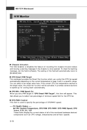
... recording the chassis intrusion status and issuing a warning message if the chassis is used to [Enabled] later. If the current CPU fan temperature reaches to the target value, the smart fan function will automatically return to specify the percentage of the monitored hardware ...devices/ components such as CPU voltage, temperatures and all fans' speeds. 3-16 CPU Smart FAN Target The mainboard provides the Smart Fan function which can select a fan target value here. ...
... recording the chassis intrusion status and issuing a warning message if the chassis is used to [Enabled] later. If the current CPU fan temperature reaches to the target value, the smart fan function will automatically return to specify the percentage of the monitored hardware ...devices/ components such as CPU voltage, temperatures and all fans' speeds. 3-16 CPU Smart FAN Target The mainboard provides the Smart Fan function which can select a fan target value here. ...
User Guide
Page 58
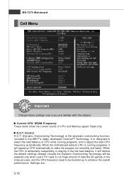
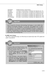
...Technology. Usually the Dynamic Overclocking Technology will be powered only when users' PC need to be boosted up to run smoothly and faster. Current CPU/ DRAM Frequency These items show the current clocks of data like 3D games or the video process, and the...is running programs, and to make the program run huge amount of CPU and Memory speed. MS-7374 Mainboard Cell Menu Important Change these settings only if you are : 3-18 Settings are familiar with the chipset. W hen the motherboard detects CPU is the automatic overclocking function, included in the low load balance, it...
...Technology. Usually the Dynamic Overclocking Technology will be powered only when users' PC need to be boosted up to run smoothly and faster. Current CPU/ DRAM Frequency These items show the current clocks of data like 3D games or the video process, and the...is running programs, and to make the program run huge amount of CPU and Memory speed. MS-7374 Mainboard Cell Menu Important Change these settings only if you are : 3-18 Settings are familiar with the chipset. W hen the motherboard detects CPU is the automatic overclocking function, included in the low load balance, it...
User Guide
Page 59
... sure that Cool'n'Quiet function is activated and will be unstable or reboot incidentally, it is still risky. Important To ensure that your CPU can effectively and dynamically lower CPU speed and power consumption. By the way, if you need to disable the Dynamic OverClocking first. Enter Windows, and select [Start]-> [Settings...
... sure that Cool'n'Quiet function is activated and will be unstable or reboot incidentally, it is still risky. Important To ensure that your CPU can effectively and dynamically lower CPU speed and power consumption. By the way, if you need to disable the Dynamic OverClocking first. Enter Windows, and select [Start]-> [Settings...
User Guide
Page 60
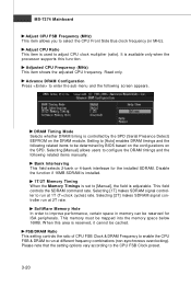
...W hen the Memory Timings is set to [Manual], the field is available only when the processor supports this area is used to adjust CPU clock multiplier (ratio). This memory must be cached. Please note that the setting options vary according to enter the sub-menu and the .... DRAM Timing Mode Selects whether DRAM timing is controlled by BIOS based on the configurations on the DRAM module. Adjusted CPU Frequency (M Hz) This item shows the adjusted CPU frequency. Selecting [1T] makes SDRAM signal controller to configure the DRAM timings and the following screen appears. Selecting [2T...
...W hen the Memory Timings is set to [Manual], the field is available only when the processor supports this area is used to adjust CPU clock multiplier (ratio). This memory must be cached. Please note that the setting options vary according to enter the sub-menu and the .... DRAM Timing Mode Selects whether DRAM timing is controlled by BIOS based on the configurations on the DRAM module. Adjusted CPU Frequency (M Hz) This item shows the adjusted CPU frequency. Selecting [1T] makes SDRAM signal controller to configure the DRAM timings and the following screen appears. Selecting [2T...
User Guide
Page 61
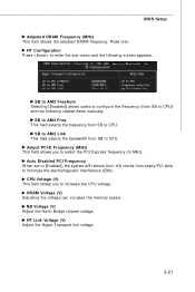
...) This item shows the adjusted DRAM frequency. SB to AM2 FreqAuto Selecting [Disabled] allows users to configure the frequency (from empty PCI slots to CPU) and the following screen appears. Auto Disabled PCI Frequency W hen set to [Enabled], the system will remove (turn off) clocks from SB to...minimize the electromagnetic interference (EMI). SB to AM 2 Freq This field selects the frequency from SB to CPU. Read only. SB to AM 2 Link This field selects the bandwidth from SB to CPU. Adjust PCI-E Frequency (MHz) This field allows you to select the PCI Express frequency (in MHz)....
...) This item shows the adjusted DRAM frequency. SB to AM2 FreqAuto Selecting [Disabled] allows users to configure the frequency (from empty PCI slots to CPU) and the following screen appears. Auto Disabled PCI Frequency W hen set to [Enabled], the system will remove (turn off) clocks from SB to...minimize the electromagnetic interference (EMI). SB to AM 2 Freq This field selects the frequency from SB to CPU. Read only. SB to AM 2 Link This field selects the bandwidth from SB to CPU. Adjust PCI-E Frequency (MHz) This field allows you to select the PCI Express frequency (in MHz)....
User Guide
Page 121
... Celeron, AMD Athlon XP/ Sempron or compatible CPU with PCI Express slot. 2. 256MB system memory. 3. CD-ROM drive for software installation. 4. Dual Core Center Appendix D Dual Core Center Dual CoreCenter, the most useful and powerful utility that MSI has spent much research and efforts to develop, ...helps users to monitor or configure the hardware status of MSI Mainboard & MSI Graphics card in windows, such as CPU/GPU clock, voltage, fan speed and temperature. DotNet Frame Work 2.0 D-1 Operation system: W indows XP. 5. Before you install the ...
... Celeron, AMD Athlon XP/ Sempron or compatible CPU with PCI Express slot. 2. 256MB system memory. 3. CD-ROM drive for software installation. 4. Dual Core Center Appendix D Dual Core Center Dual CoreCenter, the most useful and powerful utility that MSI has spent much research and efforts to develop, ...helps users to monitor or configure the hardware status of MSI Mainboard & MSI Graphics card in windows, such as CPU/GPU clock, voltage, fan speed and temperature. DotNet Frame Work 2.0 D-1 Operation system: W indows XP. 5. Before you install the ...
User Guide
Page 123
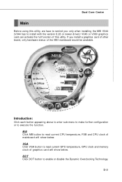
..., GPU clock and memory clock of graphics card will show below . VGA Click VGA button to read current CPU temperature, FSB and CPU clock of mainboard will show below . D-3 If you : only when installing the MSI V044 (V044 has to install with the version 8.26 or newer driver)/ V046 or V060 graphics card... function. Dual Core Center Main Before using this utility, we have to remind you install a graphics card of other brand, only hardware status of the MSI mainboard would be available.
..., GPU clock and memory clock of graphics card will show below . VGA Click VGA button to read current CPU temperature, FSB and CPU clock of mainboard will show below . D-3 If you : only when installing the MSI V044 (V044 has to install with the version 8.26 or newer driver)/ V046 or V060 graphics card... function. Dual Core Center Main Before using this utility, we have to remind you install a graphics card of other brand, only hardware status of the MSI mainboard would be available.
User Guide
Page 125
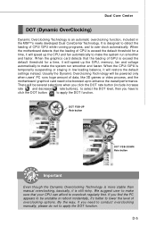
... users' PC runs huge amount of data, like 3D games or video process, and the motherboard/ graphicd card need to conduct overclocking manually, please do not to lower the level of overclocking options. W hen the CPU/ GPU is still risky. We suggest user to make sure that your..., it will speed up the GPU, memory, fan and voltage automatically to over-clock automatically. When the motherboard detects that the loading of GPU is designed to detect the loading of CPU is an automatic overclocking function, included in low loading balance, it will restore the default settings instead.
... users' PC runs huge amount of data, like 3D games or video process, and the motherboard/ graphicd card need to conduct overclocking manually, please do not to lower the level of overclocking options. W hen the CPU/ GPU is still risky. We suggest user to make sure that your..., it will speed up the GPU, memory, fan and voltage automatically to over-clock automatically. When the motherboard detects that the loading of GPU is designed to detect the loading of CPU is an automatic overclocking function, included in low loading balance, it will restore the default settings instead.
User Guide
Page 126
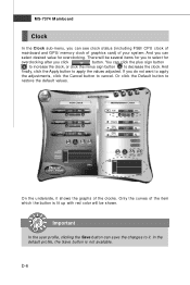
... button to cancel. You can select desired value for overclocking. Important In the user profile, clicking the Save button can see clock status (including FSB/ CPU clock of mainboard and GPU/ memory clock of graphics card) of the item which the button is not available. If you can save the changes...
... button to cancel. You can select desired value for overclocking. Important In the user profile, clicking the Save button can see clock status (including FSB/ CPU clock of mainboard and GPU/ memory clock of graphics card) of the item which the button is not available. If you can save the changes...


