User Guide
Page 2
...without notice. Netware® is a registered trademark of Microsoft Corporation. Alternatively, please try the following help resources for FAQ, technical guide, BIOS updates, driver updates, and other countries. W indows® 95/98/2000/NT/XP are registered trademarks of Novell, Inc. Award®...and we reserve the right to the correctness of NVIDIA Corporation in the United States and/or other information: http://global.msi.com.tw/index.php? Our products are registered trademarks of their respective owners. Trademarks All trademarks are registered trademarks or ...
...without notice. Netware® is a registered trademark of Microsoft Corporation. Alternatively, please try the following help resources for FAQ, technical guide, BIOS updates, driver updates, and other countries. W indows® 95/98/2000/NT/XP are registered trademarks of Novell, Inc. Award®...and we reserve the right to the correctness of NVIDIA Corporation in the United States and/or other information: http://global.msi.com.tw/index.php? Our products are registered trademarks of their respective owners. Trademarks All trademarks are registered trademarks or ...
User Guide
Page 8
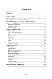
... Supply ...2-8 Back Panel ...2-10 Connectors ...2-12 Button ...2-19 Slots ...2-20 LED Status Indicators 2-25 Chapter 3 BIOS Setup 3-1 Entering Setup ...3-2 The Main Menu ...3-4 Standard CMOS Features 3-6 Advanced BIOS Features 3-8 Integrated Peripherals 3-11 Power Management Setup 3-13 H/W Monitor ...3-16 BIOS Setting Password 3-17 Cell Menu ...3-18 USERSETTINGS 3-23 Load Fail-Safe/ Optimized Defaults 3-24 Appendix...
... Supply ...2-8 Back Panel ...2-10 Connectors ...2-12 Button ...2-19 Slots ...2-20 LED Status Indicators 2-25 Chapter 3 BIOS Setup 3-1 Entering Setup ...3-2 The Main Menu ...3-4 Standard CMOS Features 3-6 Advanced BIOS Features 3-8 Integrated Peripherals 3-11 Power Management Setup 3-13 H/W Monitor ...3-16 BIOS Setting Password 3-17 Cell Menu ...3-18 USERSETTINGS 3-23 Load Fail-Safe/ Optimized Defaults 3-24 Appendix...
User Guide
Page 9
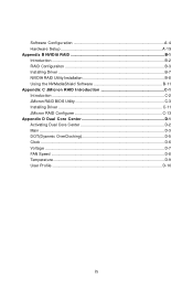
Software Configuration A-4 Hardware Setup A-19 Appendix B NVIDIA RAID B-1 Introduction ...B-2 RAID Configuraiton B-3 Installing Driver ...B-7 NVIDIA RAID Utility Installation B-8 Using the NVMediaShield Software B-11 Appendix C JM icron RAID Introduction C-1 Introduction ...C-2 JMicron RAID BIOS Utility C-3 Installing Driver C-11 JMicron RAID Configurer C-13 Appendix D Dual Core Center D-1 Activating Dual Core Center D-2 Main ...D-3 DOT(Dyanmic OverClocking D-5 Clock ...D-6 Voltage ...D-7 FAN Speed ...D-8 Temperature ...D-9 User Profile ...D-10 ix
Software Configuration A-4 Hardware Setup A-19 Appendix B NVIDIA RAID B-1 Introduction ...B-2 RAID Configuraiton B-3 Installing Driver ...B-7 NVIDIA RAID Utility Installation B-8 Using the NVMediaShield Software B-11 Appendix C JM icron RAID Introduction C-1 Introduction ...C-2 JMicron RAID BIOS Utility C-3 Installing Driver C-11 JMicron RAID Configurer C-13 Appendix D Dual Core Center D-1 Activating Dual Core Center D-2 Main ...D-3 DOT(Dyanmic OverClocking D-5 Clock ...D-6 Voltage ...D-7 FAN Speed ...D-8 Temperature ...D-9 User Profile ...D-10 ix
User Guide
Page 19
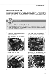
... other end of the clip to fasten the cooling set onto the retention mechanism. Hook one end of the retention mechanism. Mainboard photos shown in BIOS (Chapter 3). 2. The appearance of the CPU/ cooler installation only. Attach the CPU fan cable to purchase and install them before turning on the mainboard. 2-5 Hardware...
... other end of the clip to fasten the cooling set onto the retention mechanism. Hook one end of the retention mechanism. Mainboard photos shown in BIOS (Chapter 3). 2. The appearance of the CPU/ cooler installation only. Attach the CPU fan cable to purchase and install them before turning on the mainboard. 2-5 Hardware...
User Guide
Page 29
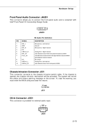
... will record this status and show a warning message on the screen. Hardware Setup Front Panel Audio Connector: JAUD1 This connector allows you must enter the BIOS utility and clear the record. Right channel Analog Port - To clear the warning, you to the chassis intrusion switch cable. L GND R JCD1 2-15 GND 1 CINTRU...
... will record this status and show a warning message on the screen. Hardware Setup Front Panel Audio Connector: JAUD1 This connector allows you must enter the BIOS utility and clear the record. Right channel Analog Port - To clear the warning, you to the chassis intrusion switch cable. L GND R JCD1 2-15 GND 1 CINTRU...
User Guide
Page 34
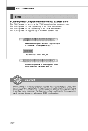
... 8.0 GB/s transfer rate. The PCI Express x 1 supports up to 4.0 GB/s transfer rate. Meanwhile, read the documentation for the expansion card, such as jumpers, switches or BIOS configuration. 2-20 The PCI Express 2.0 x 16 supports up to configure any necessary hardware or software settings for the expansion card to 250 MB/s transfer rate.
... 8.0 GB/s transfer rate. The PCI Express x 1 supports up to 4.0 GB/s transfer rate. Meanwhile, read the documentation for the expansion card, such as jumpers, switches or BIOS configuration. 2-20 The PCI Express 2.0 x 16 supports up to configure any necessary hardware or software settings for the expansion card to 250 MB/s transfer rate.
User Guide
Page 37
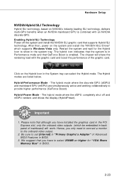
...). The Hybrid modes are simultaneously active and working collaboratively to show in BIOS. 2-23 Click on the Hybrid Icon in Performance mode and that GeForce Boost is enabled. Hardware Setup NVIDIA Hybrid SLI Technology Hybrid SLI technology, based on NVIDIA's industry-leading SLI technology, delivers multi-GPU benefits when an NVIDIA mainboard GPU is...
...). The Hybrid modes are simultaneously active and working collaboratively to show in BIOS. 2-23 Click on the Hybrid Icon in Performance mode and that GeForce Boost is enabled. Hardware Setup NVIDIA Hybrid SLI Technology Hybrid SLI technology, based on NVIDIA's industry-leading SLI technology, delivers multi-GPU benefits when an NVIDIA mainboard GPU is...
User Guide
Page 38
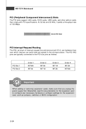
... PCI Interrupt Request Routing The IRQ, acronym of interrupt request line and pronounced I-R-Q, are typically connected to the PCI bus pins as jumpers, switches or BIOS configuration. 2-24 Meanwhile, read the documentation for the expansion card, such as follows: PCI Slot 1 PCI Slot 2 Order 1 INT W# INT X# Order 2 INT X# INT Y# Order 3 INT...
... PCI Interrupt Request Routing The IRQ, acronym of interrupt request line and pronounced I-R-Q, are typically connected to the PCI bus pins as jumpers, switches or BIOS configuration. 2-24 Meanwhile, read the documentation for the expansion card, such as follows: PCI Slot 1 PCI Slot 2 Order 1 INT W# INT X# Order 2 INT X# INT Y# Order 3 INT...
User Guide
Page 40
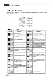
...message to the screen. Group4 Group3 Group2 Group1 Assign Resources to RAM for fast booting. Group4 Group3 Group2 Group1 Testing VGA BIOS This will start showing information about logo, processor brand name, etc... Group4 Initializing Floppy Drive Controller Group3 This will set ...low stack and boot via INT 19h. Group4 Group3 Group2 Group1 Decompressing BIOS image to all ISA. Group4 Group3 Group2 Group1 Testing Base and Extended Memory Testing base memory from 240K to identify system problems...
...message to the screen. Group4 Group3 Group2 Group1 Assign Resources to RAM for fast booting. Group4 Group3 Group2 Group1 Testing VGA BIOS This will start showing information about logo, processor brand name, etc... Group4 Initializing Floppy Drive Controller Group3 This will set ...low stack and boot via INT 19h. Group4 Group3 Group2 Group1 Decompressing BIOS image to all ISA. Group4 Group3 Group2 Group1 Testing Base and Extended Memory Testing base memory from 240K to identify system problems...
User Guide
Page 41
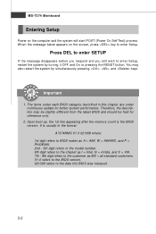
You may need to run SETUP. ² You want to configure the system for customized features. 3-1 Chapter 3 BIOS Setup BIOS Setup This chapter provides information on the screen during the system booting up, and requests you to run the Setup program when: ² An error message appears on the BIOS Setup program and allows you to change the default settings for optimum use.
You may need to run SETUP. ² You want to configure the system for customized features. 3-1 Chapter 3 BIOS Setup BIOS Setup This chapter provides information on the screen during the system booting up, and requests you to run the Setup program when: ² An error message appears on the BIOS Setup program and allows you to change the default settings for optimum use.
User Guide
Page 42
... MS = all standard customers. You may be slightly different from the latest BIOS and should be held for better system performance. Important 1. The items under each BIOS category described in the format: A7374NMS V1.0 021308 where: 1st digit refers to BIOS maker as A = AMI, W = AWARD, and P = PHOENIX. 2nd ... chapter are under continuous update for reference only. 2. Upon boot-up, the 1st line appearing after the memory count is usually in this BIOS was released. 3-2 W hen the message below appears on the computer and the system will start POST (Power On Self Test) process. ...
... MS = all standard customers. You may be slightly different from the latest BIOS and should be held for better system performance. Important 1. The items under each BIOS category described in the format: A7374NMS V1.0 021308 where: 1st digit refers to BIOS maker as A = AMI, W = AWARD, and P = PHOENIX. 2nd ... chapter are under continuous update for reference only. 2. Upon boot-up, the 1st line appearing after the memory count is usually in this BIOS was released. 3-2 W hen the message below appears on the computer and the system will start POST (Power On Self Test) process. ...
User Guide
Page 43
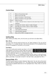
...) to highlight the field and press to use the arrow keys ( ↑↓ ) to field within a sub-menu. You can call up this field. BIOS Setup Control Keys Enter> Move to the previous item Move to the next item Move to the item in the right hand Select the item...main menu, just press the . The on-line description of the screen. A sub-menu contains additional options for the highlighted item. General Help The BIOS setup program provides a General Help screen. You can use and the possible selections for a field parameter. Main Menu The main menu lists the setup ...
...) to highlight the field and press to use the arrow keys ( ↑↓ ) to field within a sub-menu. You can call up this field. BIOS Setup Control Keys Enter> Move to the previous item Move to the next item Move to the item in the right hand Select the item...main menu, just press the . The on-line description of the screen. A sub-menu contains additional options for the highlighted item. General Help The BIOS setup program provides a General Help screen. You can use and the possible selections for a field parameter. Main Menu The main menu lists the setup ...
User Guide
Page 44
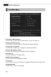
... control and overclocking. USER SETTINGS Use this menu to specify your PC health status. Power Management Setup Use this menu to save or load settings. 3-4 BIOS Setting Password Use this menu for basic system configurations, such as time, date etc. MS-7374 Mainboard The Main Menu Standard CMOS Features Use this...
... control and overclocking. USER SETTINGS Use this menu to specify your PC health status. Power Management Setup Use this menu to save or load settings. 3-4 BIOS Setting Password Use this menu for basic system configurations, such as time, date etc. MS-7374 Mainboard The Main Menu Standard CMOS Features Use this...

User Guide
Page 45
Save & Exit Setup Save changes to CMOS and exit setup. Exit Without Saving Abandon all changes and exit setup. 3-5 Load Optimized Defaults Use this menu to load the default values set by the BIOS vendor for optimal performance of the mainboard. BIOS Setup Load Fail-Safe Defaults Use this menu to load the default values set by the mainboard manufacturer specifically for stable system performance.
Save & Exit Setup Save changes to CMOS and exit setup. Exit Without Saving Abandon all changes and exit setup. 3-5 Load Optimized Defaults Use this menu to load the default values set by the BIOS vendor for optimal performance of the mainboard. BIOS Setup Load Fail-Safe Defaults Use this menu to load the default values set by the mainboard manufacturer specifically for stable system performance.
User Guide
Page 46
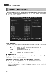
... the item and then use the or keys to select the value you want (usually the current time). year The year can be adjusted by BIOS. day Day of the week, from Jan. The time format is . Date (MM:DD:YY) This allows you to set the system time that you...
... the item and then use the or keys to select the value you want (usually the current time). year The year can be adjusted by BIOS. day Day of the week, from Jan. The time format is . Date (MM:DD:YY) This allows you to set the system time that you...
User Guide
Page 47
... the HD devices to the IDE/ SATA/ E-SATA connector on the mainboard. Hard Disk S.M.A.R.T. This sub-menu shows the CPU information, BIOS version and memory status of floppy drives installed. BIOS Setup LBA/Large M ode This allows you to activate the S.M.A.R.T. (Self-Monitoring Analysis & Reporting Technology) capability for the hard disks. Setting...
... the HD devices to the IDE/ SATA/ E-SATA connector on the mainboard. Hard Disk S.M.A.R.T. This sub-menu shows the CPU information, BIOS version and memory status of floppy drives installed. BIOS Setup LBA/Large M ode This allows you to activate the S.M.A.R.T. (Self-Monitoring Analysis & Reporting Technology) capability for the hard disks. Setting...
User Guide
Page 48
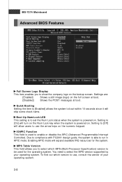
... numeric keypad. IOAPIC Function This field is powered on . Due to compliance with PC2001 design guide, the system is powered on . MS-7374 Mainboard Advanced BIOS Features Full Screen Logo Display This item enables you to select which version to use the arrow keys on the bootup screen. Quick Booting Setting...
... numeric keypad. IOAPIC Function This field is powered on . Due to compliance with PC2001 design guide, the system is powered on . MS-7374 Mainboard Advanced BIOS Features Full Screen Logo Display This item enables you to select which version to use the arrow keys on the bootup screen. Quick Booting Setting...
User Guide
Page 49
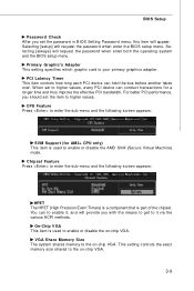
... hold the bus before another takes over. Chipset Feature Press to it , and will request the password when enter both the operating system and the BIOS setup menu. Selecting [always] will provide you with the means to get to enter the sub-menu and the following screen appears: SVM Support (for... size shared to enable it via the various ACPI methods. W hen set to higher values. On-Chip VGA This item is your primary graphics adapter. BIOS Setup Password Check After you set the password in BIOS Setting Password menu, this item will request the password when enter the...
... hold the bus before another takes over. Chipset Feature Press to it , and will request the password when enter both the operating system and the BIOS setup menu. Selecting [always] will provide you with the means to get to enter the sub-menu and the following screen appears: SVM Support (for... size shared to enable it via the various ACPI methods. W hen set to higher values. On-Chip VGA This item is your primary graphics adapter. BIOS Setup Password Check After you set the password in BIOS Setting Password menu, this item will request the password when enter the...
User Guide
Page 50
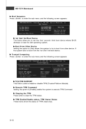
... sub-menu and the following screen appears: 1st/ 2nd/ 3rd Boot Device The items allow you to set the first/ second/ third boot device where BIOS attempts to load the disk operating system. TPM Enable/Disable status, TPM Owner Status These items show the status of TPM (read only). 3-10 MS...
... sub-menu and the following screen appears: 1st/ 2nd/ 3rd Boot Device The items allow you to set the first/ second/ third boot device where BIOS attempts to load the disk operating system. TPM Enable/Disable status, TPM Owner Status These items show the status of TPM (read only). 3-10 MS...
User Guide
Page 51
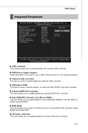
... the onboard USB controller. LAN Option ROM This item is used to decide whether to invoke the Boot ROM of the LAN controller. Integrated Peripherals BIOS Setup USB Controller This setting allows you to enable/disable the onboard IEEE1394 controller.
... the onboard USB controller. LAN Option ROM This item is used to decide whether to invoke the Boot ROM of the LAN controller. Integrated Peripherals BIOS Setup USB Controller This setting allows you to enable/disable the onboard IEEE1394 controller.


