

Owner's Manual
Page 2
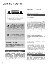
OWNER'S MANUAL PLASMA TV Please read this manual carefully before operating your set and retain it for future reference. 42PJ250 50PJ250 50PK250 60PK250 60PK280 60PK290 42PJ340 50PJ340 42PJ350 50PJ350 50PK350 50PK340 50PK540 60PK540 P/NO : SAC34173302 (1004-REV02) 42PJ550 50PJ550 50PK550 60PK550 42PJ350C 50PJ350C 50PK550C 60PK550C www.lg.com
OWNER'S MANUAL PLASMA TV Please read this manual carefully before operating your set and retain it for future reference. 42PJ250 50PJ250 50PK250 60PK250 60PK280 60PK290 42PJ340 50PJ340 42PJ350 50PJ350 50PK350 50PK340 50PK540 60PK540 P/NO : SAC34173302 (1004-REV02) 42PJ550 50PJ550 50PK550 60PK550 42PJ350C 50PJ350C 50PK550C 60PK550C www.lg.com
Owner's Manual
Page 3
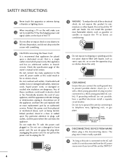
...radio frequency energy and, if not installed and used in particular, specifies that interference will not occur in a residential installation. NOTE TO CABLE/TV INSTALLER This reminder is connected. - If this equipment does cause harmful interference to the point of the device). Consult the dealer or an ...the party responsible for help. This equipment generates, uses and can be determined by turning the equipment off and on a circuit different from LG Electronics. Connect the equipment to an outlet on , the user is intended to alert the user to comply with the limits for proper ...
...radio frequency energy and, if not installed and used in particular, specifies that interference will not occur in a residential installation. NOTE TO CABLE/TV INSTALLER This reminder is connected. - If this equipment does cause harmful interference to the point of the device). Consult the dealer or an ...the party responsible for help. This equipment generates, uses and can be determined by turning the equipment off and on a circuit different from LG Electronics. Connect the equipment to an outlet on , the user is intended to alert the user to comply with the limits for proper ...
Owner's Manual
Page 5
... it is not disconnected from physical or mechanical abuse, such as this could result in a door, or walked upon a dedicated circuit; a TV with the power cord plugged in fire or electric shock. Check the specification page of fire or electrical shock, do not drop onto the screen...or damaged or cracked wire insulation are not possible, have the cord replaced with wet hands. Do not make sure 12 not to install the TV by an authorized servicer. Periodically examine the cord of the appliance, and have a qualified electrician install a separate circuit breaker. Do not use ...
... it is not disconnected from physical or mechanical abuse, such as this could result in a door, or walked upon a dedicated circuit; a TV with the power cord plugged in fire or electric shock. Check the specification page of fire or electrical shock, do not drop onto the screen...or damaged or cracked wire insulation are not possible, have the cord replaced with wet hands. Do not make sure 12 not to install the TV by an authorized servicer. Periodically examine the cord of the appliance, and have a qualified electrician install a separate circuit breaker. Do not use ...
Owner's Manual
Page 6
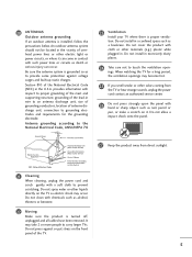
... 26 Do not press strongly upon the panel with hand or sharp object such as nail, pencil or pen, or make a scratch on the TV as electric shock may take 2 or more people to prevent scratching. Do not press against voltage surges and built-up static charges. An outdoor ... provides information with respect to proper grounding of the mast and supporting structure, grounding of the lead-in contact with a soft cloth to carry larger TVs. Do not spray water or other electric light or power circuits, or where it . Do not install in . 20 ANTENNAS Outdoor antenna grounding If...
... 26 Do not press strongly upon the panel with hand or sharp object such as nail, pencil or pen, or make a scratch on the TV as electric shock may take 2 or more people to prevent scratching. Do not press against voltage surges and built-up static charges. An outdoor ... provides information with respect to proper grounding of the mast and supporting structure, grounding of the lead-in contact with a soft cloth to carry larger TVs. Do not spray water or other electric light or power circuits, or where it . Do not install in . 20 ANTENNAS Outdoor antenna grounding If...
Owner's Manual
Page 7
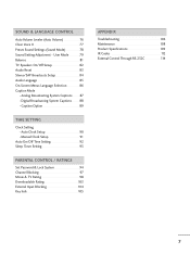
...Mode 69 Manual Picture Adjustment - Add / Delete Channel (Manual Tuning 44 - CONTENTS WARNING / CAUTION 2 SAFETY INSTRUCTIONS 3 FEATURE OF THIS TV 8 PREPARATION Accessories 9 Front Panel Information 10 Back Panel Information 13 Stand Instruction 15 Cable Management 17 Desktop Pedestal Installation 18 Swivel Stand 18 ...VESA Wall Mounting 19 Securing the TV to the wall to prevent falling when the TV is used on a stand 20 Antenna or Cable Connection 21 EXTERNAL EQUIPMENT SETUP HD Receiver Setup ...
...Mode 69 Manual Picture Adjustment - Add / Delete Channel (Manual Tuning 44 - CONTENTS WARNING / CAUTION 2 SAFETY INSTRUCTIONS 3 FEATURE OF THIS TV 8 PREPARATION Accessories 9 Front Panel Information 10 Back Panel Information 13 Stand Instruction 15 Cable Management 17 Desktop Pedestal Installation 18 Swivel Stand 18 ...VESA Wall Mounting 19 Securing the TV to the wall to prevent falling when the TV is used on a stand 20 Antenna or Cable Connection 21 EXTERNAL EQUIPMENT SETUP HD Receiver Setup ...
Owner's Manual
Page 8
.../Off Time Setting 92 Sleep Timer Setting 93 PARENTAL CONTROL / RATINGS Set Password & Lock System 94 Channel Blocking 97 Movie & TV Rating 98 Downloadable Rating 103 External Input Blocking 104 Key lock 105 APPENDIX Troubleshooting 106 Maintenance 108 Product Specifications 109 IR Codes 112... External Control Through RS-232C 114 7 User Mode 79 Balance 81 TV Speakers On/Off Setup 82 Audio Reset 83 Stereo/SAP Broadcasts Setup 84 Audio Language 85 On-Screen Menus Language Selection 86 ...
.../Off Time Setting 92 Sleep Timer Setting 93 PARENTAL CONTROL / RATINGS Set Password & Lock System 94 Channel Blocking 97 Movie & TV Rating 98 Downloadable Rating 103 External Input Blocking 104 Key lock 105 APPENDIX Troubleshooting 106 Maintenance 108 Product Specifications 109 IR Codes 112... External Control Through RS-232C 114 7 User Mode 79 Balance 81 TV Speakers On/Off Setup 82 Audio Reset 83 Stereo/SAP Broadcasts Setup 84 Audio Language 85 On-Screen Menus Language Selection 86 ...

Owner's Manual
Page 9
...This phenomenon is three preset picture and audio settings. This TV contains the detailed calibrations necessary for professional certification by the user to experience the best their LG HDTV has to music on the screen. Please contact your TV through the ISFccc mode. "Dolby "and the double-D symbol... are trademarks or registered trademarks of your TV screen for a prolonged period (2 or more hours for ...
...This phenomenon is three preset picture and audio settings. This TV contains the detailed calibrations necessary for professional certification by the user to experience the best their LG HDTV has to music on the screen. Please contact your TV through the ISFccc mode. "Dolby "and the double-D symbol... are trademarks or registered trademarks of your TV screen for a prolonged period (2 or more hours for ...

Owner's Manual
Page 10
... available for all models.) Place the ferrite core close to reduce the elec- Install the Ferrite core on the exterior only with your TV. close to the wall plug. 9 PREPARATION PREPARATION ACCESSORIES Ensure that may interfere with ferrite cores to reduce the electromag- available for stand...Cable When using the VGA (D-sub 15 pin cable) PC connection, the user must use shielded signal interface cables with the (Black) TV. If an accessory is not close to the wall plug. Ferrite Core tromagnetic waves that the following accessories are included with the polishing ...
... available for all models.) Place the ferrite core close to reduce the elec- Install the Ferrite core on the exterior only with your TV. close to the wall plug. 9 PREPARATION PREPARATION ACCESSORIES Ensure that may interfere with ferrite cores to reduce the electromag- available for stand...Cable When using the VGA (D-sub 15 pin cable) PC connection, the user must use shielded signal interface cables with the (Black) TV. If an accessory is not close to the wall plug. Ferrite Core tromagnetic waves that the following accessories are included with the polishing ...
Owner's Manual
Page 11
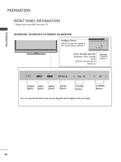
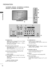
PREPARATION PREPARATION FRONT PANEL INFORMATION I Image shown may differ from your finger. 10 Remote Control Sensor ENTER VOL CH POWER INPUT Button Button MENU Button ENTER Button VOLUME Buttons CHANNEL Buttons ENTER You can operate the button just by touching the button lightly with your TV. 50/60PK550, 50/60PK540, 42/50PJ550, 50/60PK550C Intelligent Sensor Adjusts picture according to the surrounding conditions. The LED is off while the TV remains on. ENTER VOL CH Power/Standby Indicator Illuminates red in standby mode.
PREPARATION PREPARATION FRONT PANEL INFORMATION I Image shown may differ from your finger. 10 Remote Control Sensor ENTER VOL CH POWER INPUT Button Button MENU Button ENTER Button VOLUME Buttons CHANNEL Buttons ENTER You can operate the button just by touching the button lightly with your TV. 50/60PK550, 50/60PK540, 42/50PJ550, 50/60PK550C Intelligent Sensor Adjusts picture according to the surrounding conditions. The LED is off while the TV remains on. ENTER VOL CH Power/Standby Indicator Illuminates red in standby mode.
Owner's Manual
Page 12
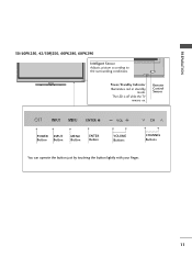
Remote Control Sensor ENTER VOL CH POWER INPUT Button Button MENU Button ENTER Button VOLUME Buttons CHANNEL Buttons ENTER You can operate the button just by touching the button lightly with your finger. 11 PREPARATION 50/60PK250, 42/50PJ250, 60PK280, 60PK290 Intelligent Sensor Adjusts picture according to the surrounding conditions. ENTER VOL CH Power/Standby Indicator Illuminates red in standby mode. The LED is off while the TV remains on.
Remote Control Sensor ENTER VOL CH POWER INPUT Button Button MENU Button ENTER Button VOLUME Buttons CHANNEL Buttons ENTER You can operate the button just by touching the button lightly with your finger. 11 PREPARATION 50/60PK250, 42/50PJ250, 60PK280, 60PK290 Intelligent Sensor Adjusts picture according to the surrounding conditions. ENTER VOL CH Power/Standby Indicator Illuminates red in standby mode. The LED is off while the TV remains on.
Owner's Manual
Page 13
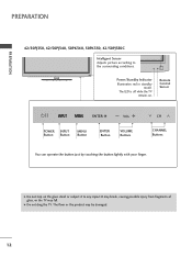
The floor or the product may fall. PREPARATION PREPARATION 42/50PJ350, 42/50PJ340, 50PK340, 50PK350, 42/50PJ350C Intelligent Sensor Adjusts picture according to any impact.It may break, causing possible injury from fragments of glass, or the TV may be damaged. 12 G Do not step on . Remote Control Sensor ENTER VOL CH VOL...Button ENTER Button VOLUME Buttons CHANNEL Buttons You can operate the button just by touching the button lightly with your finger. G Do not drag the TV. ENTER VOL CH Power/Standby Indicator Illuminates red in standby mode. The LED is off while the...
The floor or the product may fall. PREPARATION PREPARATION 42/50PJ350, 42/50PJ340, 50PK340, 50PK350, 42/50PJ350C Intelligent Sensor Adjusts picture according to any impact.It may break, causing possible injury from fragments of glass, or the TV may be damaged. 12 G Do not step on . Remote Control Sensor ENTER VOL CH VOL...Button ENTER Button VOLUME Buttons CHANNEL Buttons You can operate the button just by touching the button lightly with your finger. G Do not drag the TV. ENTER VOL CH Power/Standby Indicator Illuminates red in standby mode. The LED is off while the...
Owner's Manual
Page 14
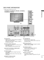
...updates. 10 Power Cord Socket For operation with amps and home theater systems. Note: In standby mode, this jack. Connect cable signals to operate the TV on DC power. 13 Doesn't support 480i. Uses a D-sub 15 pin cable (VGA cable). 5 REMOTE CONTROL IN PORT For a wired remote ... video and Digital audio. R VIDEO L/MONO AUDIO R HDMI IN 3 SERVICE ONLY R R PREPARATION BACK PANEL INFORMATION I Image shown may differ from your TV. 42/50PJ250, 50/60PK250, 60PK280, 42/50PJ340, 50/60PK540, 50PK340 9 1 7 10 AV IN 2 2 4 5 7 OPTICAL DIGITAL AUDIO OUT AUDIO IN (RGB/DVI) REMOTE CONTROL IN AV IN...
...updates. 10 Power Cord Socket For operation with amps and home theater systems. Note: In standby mode, this jack. Connect cable signals to operate the TV on DC power. 13 Doesn't support 480i. Uses a D-sub 15 pin cable (VGA cable). 5 REMOTE CONTROL IN PORT For a wired remote ... video and Digital audio. R VIDEO L/MONO AUDIO R HDMI IN 3 SERVICE ONLY R R PREPARATION BACK PANEL INFORMATION I Image shown may differ from your TV. 42/50PJ250, 50/60PK250, 60PK280, 42/50PJ340, 50/60PK540, 50PK340 9 1 7 10 AV IN 2 2 4 5 7 OPTICAL DIGITAL AUDIO OUT AUDIO IN (RGB/DVI) REMOTE CONTROL IN AV IN...
Owner's Manual
Page 15
... listening to this port doesn't work. 3 RS-232C IN (CONTROL & SERVICE) PORT Used by third party devices. Supports HD. Connect cable signals to operate the TV on DC power. 14 Supports HD video and Digital audio. Caution: Never attempt to this jack. 9 USB IN Used for analog PC audio input. Uses...
... listening to this port doesn't work. 3 RS-232C IN (CONTROL & SERVICE) PORT Used by third party devices. Supports HD. Connect cable signals to operate the TV on DC power. 14 Supports HD video and Digital audio. Caution: Never attempt to this jack. 9 USB IN Used for analog PC audio input. Uses...
Owner's Manual
Page 16
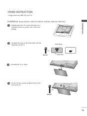
Installation (Except 60PK250, 60PK540, 60PK550, 60PK280, 60PK290, 60PK550C) 1 Carefully place the TV screen side down on a cushioned surface to protect the screen from your TV. PREPARATION STAND INSTRUCTION I Image shown may differ from damage. 2 Assemble the parts of the Stand Body with the Stand Base of the TV. x 4 M4x28 15 x 3 M5x14 Stand Body Stand Base 3 Assemble the TV as shown. 4 Fix the 4 bolts securely using the holes in the back of the TV.
Installation (Except 60PK250, 60PK540, 60PK550, 60PK280, 60PK290, 60PK550C) 1 Carefully place the TV screen side down on a cushioned surface to protect the screen from your TV. PREPARATION STAND INSTRUCTION I Image shown may differ from damage. 2 Assemble the parts of the Stand Body with the Stand Base of the TV. x 4 M4x28 15 x 3 M5x14 Stand Body Stand Base 3 Assemble the TV as shown. 4 Fix the 4 bolts securely using the holes in the back of the TV.
Owner's Manual
Page 17
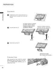
... cover over the hole for the stand. Press the PROTECTION COVER into the TV until you hear it click. 16 PROTECTION COVER (Fix a Guide to protect the screen from damage. 2 Loose the bolts from TV. (42/50PJ250, 50PK250, 42/50PJ340, 42/50PJ350, 50PK350, 50PK340, 50PK540, 42/50PJ550, 50PK550, 42/50PJ350C, 50PK550C) (60PK250, 60PK540...
... cover over the hole for the stand. Press the PROTECTION COVER into the TV until you hear it click. 16 PROTECTION COVER (Fix a Guide to protect the screen from damage. 2 Loose the bolts from TV. (42/50PJ250, 50PK250, 42/50PJ340, 42/50PJ350, 50PK350, 50PK340, 50PK540, 42/50PJ550, 50PK550, 42/50PJ350C, 50PK550C) (60PK250, 60PK540...

Owner's Manual
Page 18
CABLE HOLDER 17 PREPARATION CABLE MANAGEMENT I Image shown may differ from your TV. 1 After connecting the cables as necessary, install CABLE HOLDER as shown and bundle the cables. To connect additional equipment, see EXTERNAL EQUIPMENT SETUP section.
CABLE HOLDER 17 PREPARATION CABLE MANAGEMENT I Image shown may differ from your TV. 1 After connecting the cables as necessary, install CABLE HOLDER as shown and bundle the cables. To connect additional equipment, see EXTERNAL EQUIPMENT SETUP section.

Owner's Manual
Page 19
For proper ventilation, allow a clearance of heat source. G Do not mount near or above any type of 4 inches on all models.) After installing the TV, you can adjust the TV manually to the left or right direction by following the clearance recommendations. SWIVEL STAND (This feature is not available for all four sides from your viewing position. 18 PREPARATION PREPARATION DESKTOP PEDESTAL INSTALLATION I Image shown may differ from the wall. 4 inches 4 inches 4 inches 4 inches CAUTION G Ensure adequate ventilation by 20 degrees to suit your TV.
For proper ventilation, allow a clearance of heat source. G Do not mount near or above any type of 4 inches on all models.) After installing the TV, you can adjust the TV manually to the left or right direction by following the clearance recommendations. SWIVEL STAND (This feature is not available for all four sides from your viewing position. 18 PREPARATION PREPARATION DESKTOP PEDESTAL INSTALLATION I Image shown may differ from the wall. 4 inches 4 inches 4 inches 4 inches CAUTION G Ensure adequate ventilation by 20 degrees to suit your TV.
Owner's Manual
Page 20
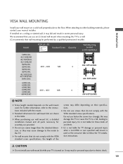
... TV to electric shock. 19 CAUTION G Do not install your wall mount kit while your nearest installer. LG recommends that do not comply with the VESA standard screw specifications, the length of accidents. Model VESA (A * B) A Standard Screw Quantity B Wall Mounting bracket (sold separately) 50PK550, 42/50PJ340 ... longer then the standard dimension, as they may fall , leading to the TV. G Do not use fasten the screws too strongly, this may result in severe personal injury. LG is not liable for TV damage or personal injury when a non-VESA or non specified wall mount is...
... TV to electric shock. 19 CAUTION G Do not install your wall mount kit while your nearest installer. LG recommends that do not comply with the VESA standard screw specifications, the length of accidents. Model VESA (A * B) A Standard Screw Quantity B Wall Mounting bracket (sold separately) 50PK550, 42/50PJ340 ... longer then the standard dimension, as they may fall , leading to the TV. G Do not use fasten the screws too strongly, this may result in severe personal injury. LG is not liable for TV damage or personal injury when a non-VESA or non specified wall mount is...
Owner's Manual
Page 21
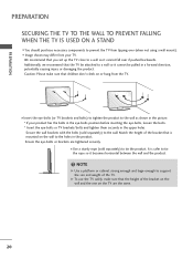
... a sturdy rope (sold separately) to the wall. Caution: Please make sure that the height of the bracket on the wall and the one on the TV are tightened securely. Secure the wall brackets with the bolts (sold separately) to tie the product. I You should purchase necessary components to a wall so it... G Use a platform or cabinet strong enough and large enough to a wall so it becomes horizontal between the wall and the product. ! G To use the TV safely, make sure that is safer to tie the rope so it cannot be attached to support the size and weight of the bracket that ...
... a sturdy rope (sold separately) to the wall. Caution: Please make sure that the height of the bracket on the wall and the one on the TV are tightened securely. Secure the wall brackets with the bolts (sold separately) to tie the product. I You should purchase necessary components to a wall so it... G Use a platform or cabinet strong enough and large enough to a wall so it becomes horizontal between the wall and the product. ! G To use the TV safely, make sure that is safer to tie the rope so it cannot be attached to support the size and weight of the bracket that ...
Owner's Manual
Page 22
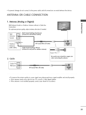
...adjust antenna direction if needed. Wall Antenna Socket Multi-family Dwellings/Apartments (Connect to bend the copper wire when connecting the antenna. Cable Cable TV Wall Jack RF Coaxial Wire (75 ohm) Single-family Dwellings /Houses (Connect to wall jack for outdoor antenna) ANTENNA /CABLE IN Copper ... to the power outlet until all connections are made between the devices. I If the antenna is not installed properly, contact your dealer for two TV's, install a 2-Way Signal Splitter. RF Coaxial Wire (75 ohm) ANTENNA /CABLE IN I To prevent damage do not connect to be split for...
...adjust antenna direction if needed. Wall Antenna Socket Multi-family Dwellings/Apartments (Connect to bend the copper wire when connecting the antenna. Cable Cable TV Wall Jack RF Coaxial Wire (75 ohm) Single-family Dwellings /Houses (Connect to wall jack for outdoor antenna) ANTENNA /CABLE IN Copper ... to the power outlet until all connections are made between the devices. I If the antenna is not installed properly, contact your dealer for two TV's, install a 2-Way Signal Splitter. RF Coaxial Wire (75 ohm) ANTENNA /CABLE IN I To prevent damage do not connect to be split for...


