
Owners Manual
Page 2
...us.lge.com 2 This equipment generates, uses and can be determined by turning the equipment off and on a circuit different from LG Electronics Corporation. If this product's compliance is provided to call the CATV system installer's attention to the point of the National ...enclosure that the cable ground shall be of sufficient magnitude to radio communications. U.S.A. The exclamation point within an equilateral triangle is connected. - The code provides guidelines for this equipment does cause harmful interference to radio or television reception, which the receiver is ...
...us.lge.com 2 This equipment generates, uses and can be determined by turning the equipment off and on a circuit different from LG Electronics Corporation. If this product's compliance is provided to call the CATV system installer's attention to the point of the National ...enclosure that the cable ground shall be of sufficient magnitude to radio communications. U.S.A. The exclamation point within an equilateral triangle is connected. - The code provides guidelines for this equipment does cause harmful interference to radio or television reception, which the receiver is ...
Owners Manual
Page 5
... . . . . . .8 Installation Accessories 9 Kensington Security System(Options) .9 Installation Instruction 10 Please set it up carefully so the product doesn't fall over 12 External Equipment Connections . .13~16 Antenna Connection 13 VCR Setup 14 Cable TV Setup 14 External A/V Source Setup 15 DVD Setup 15 DTV Setup 16 PC Setup 16 Operation TV Operation...
... . . . . . .8 Installation Accessories 9 Kensington Security System(Options) .9 Installation Instruction 10 Please set it up carefully so the product doesn't fall over 12 External Equipment Connections . .13~16 Antenna Connection 13 VCR Setup 14 Cable TV Setup 14 External A/V Source Setup 15 DVD Setup 15 DTV Setup 16 PC Setup 16 Operation TV Operation...

Owners Manual
Page 7
Connection Options Introduction 15LC1R* ANTENNA INPUT PC SOUND PC INPUT JACK INPUT COMPONENT (DTV/DVD IN) AUDIO PC INPUT ANT IN ( 75 ) PC SOUND AC INPUT H/P VIDEO IN* S-VIDEO AC INPUT COMPONENT (DTV/DVD IN) ((480i/480p), Audio) S-VIDEO HEADPHONE AUDIO/VIDEO INPUT JACK INPUT 20LC1R* ANTENNA INPUT FOR SERVICE JACK COMPONENT (DTV/DVD IN) AUDIO FOR SERVICE ANT IN ( 75 ) AC INPUT H/P VIDEO IN S-VIDEO AC INPUT AUDIO/VIDEO S-VIDEO HEADPHONE COMPONENT (DTV/DVD IN) INPUT INPUT JACK ((480i/480p), Audio) 7
Connection Options Introduction 15LC1R* ANTENNA INPUT PC SOUND PC INPUT JACK INPUT COMPONENT (DTV/DVD IN) AUDIO PC INPUT ANT IN ( 75 ) PC SOUND AC INPUT H/P VIDEO IN* S-VIDEO AC INPUT COMPONENT (DTV/DVD IN) ((480i/480p), Audio) S-VIDEO HEADPHONE AUDIO/VIDEO INPUT JACK INPUT 20LC1R* ANTENNA INPUT FOR SERVICE JACK COMPONENT (DTV/DVD IN) AUDIO FOR SERVICE ANT IN ( 75 ) AC INPUT H/P VIDEO IN S-VIDEO AC INPUT AUDIO/VIDEO S-VIDEO HEADPHONE COMPONENT (DTV/DVD IN) INPUT INPUT JACK ((480i/480p), Audio) 7
Owners Manual
Page 9
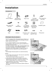
..." when when it for wall 2-Ring spacers mount rack (20LC1R* only) Fixing screw Kensington Security System - For the detailed installation and use of time. NOTES a. Connect the Kensington Security System cable as shown below. 15LC1R* - The Kensington Security System is nothing wrong with a Kensington Security System connector on the monitor's performance...
..." when when it for wall 2-Ring spacers mount rack (20LC1R* only) Fixing screw Kensington Security System - For the detailed installation and use of time. NOTES a. Connect the Kensington Security System cable as shown below. 15LC1R* - The Kensington Security System is nothing wrong with a Kensington Security System connector on the monitor's performance...

Owners Manual
Page 11
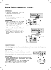
For the best reception an outdoor aerial should be somewhat different from your set. ( ) Positioning your display Adjust the position of TV 1. To connect an additional equipment, see the External Equipment Connections section. 3. Connect the power cord. Note: Here shown may be used. 2. Installation Instruction Continued Installation Connection of the panel in various ways for maximum comfort. • Tilt range 12 Be careful that your hands are not pressed down when tilting the screen. 11 Connect the aerial cable to the socket marked +75 Ω on the back.
For the best reception an outdoor aerial should be somewhat different from your set. ( ) Positioning your display Adjust the position of TV 1. To connect an additional equipment, see the External Equipment Connections section. 3. Connect the power cord. Note: Here shown may be used. 2. Installation Instruction Continued Installation Connection of the panel in various ways for maximum comfort. • Tilt range 12 Be careful that your hands are not pressed down when tilting the screen. 11 Connect the aerial cable to the socket marked +75 Ω on the back.

Owners Manual
Page 13
... signal amplifier to the antenna as shown below. (Use the correct type of antenna cable for connection. If signal needs to the antenna jack on the TV. - External Equipment Connections Installation Antenna Connection - For optimum picture quality, adjust antenna direction. If using 75Ω round cable, do not...shown to tighten. 75Ω Round Cable Copper Wire NPUT ANT IN ( 75 ) Apartment Buildings 300Ω Flat Wire Wall Connection Jack Antenna Converter Antenna Jack - VHF Antenna Turn clockwise to get better picture qual- It may cause poor picture quality. This type...
... signal amplifier to the antenna as shown below. (Use the correct type of antenna cable for connection. If signal needs to the antenna jack on the TV. - External Equipment Connections Installation Antenna Connection - For optimum picture quality, adjust antenna direction. If using 75Ω round cable, do not...shown to tighten. 75Ω Round Cable Copper Wire NPUT ANT IN ( 75 ) Apartment Buildings 300Ω Flat Wire Wall Connection Jack Antenna Converter Antenna Jack - VHF Antenna Turn clockwise to get better picture qual- It may cause poor picture quality. This type...
Owners Manual
Page 14
... = white, and Audio Right = red). 2. Select channels with the cable box remote control. 2 1 (R) AUDIO (L) VIDEO TV VCR RF Cable Cable Box 14 Connect the audio/video output jacks on rear panel, select the Video external input source.) COMPONENT (DTV/DVD IN) AUDIO PC INPUT ANT IN ( 75 ) PC... SOUND Typical Antennas ANT IN H/P VIDEO IN S-VIDEO 2 1 ANT OUT S-VIDEO OUT Direct Connection CH3 IN CH4 VIDEO (R) AUDIO(L) VCR COMPONENT (DTV/DVD IN) AUDIO PC INPUT ANT IN ( 75 ) PC SOUND H/P VIDEO IN S-VIDEO 2 Typical Antennas ...
... = white, and Audio Right = red). 2. Select channels with the cable box remote control. 2 1 (R) AUDIO (L) VIDEO TV VCR RF Cable Cable Box 14 Connect the audio/video output jacks on rear panel, select the Video external input source.) COMPONENT (DTV/DVD IN) AUDIO PC INPUT ANT IN ( 75 ) PC... SOUND Typical Antennas ANT IN H/P VIDEO IN S-VIDEO 2 1 ANT OUT S-VIDEO OUT Direct Connection CH3 IN CH4 VIDEO (R) AUDIO(L) VCR COMPONENT (DTV/DVD IN) AUDIO PC INPUT ANT IN ( 75 ) PC SOUND H/P VIDEO IN S-VIDEO 2 Typical Antennas ...
Owners Manual
Page 15
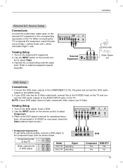
...IN) AUDIO PC INPUT ANT IN ( 75 ) PC SOUND H/P VIDEO IN S-VIDEO External Equipment R AUDIO L VIDEO Camcorder Video Game set DVD Setup Connections 1. If your DVD player does not have component video output, use S-Video. Refer to the corresponding input jacks on the TV. Use the INPUT button... on the TV. tions. (If connected to S-VIDEO on the remote con- ment. Viewing Setup 1. Use the INPUT button on rear panel, select the Video external input source.) COMPONENT...
...IN) AUDIO PC INPUT ANT IN ( 75 ) PC SOUND H/P VIDEO IN S-VIDEO External Equipment R AUDIO L VIDEO Camcorder Video Game set DVD Setup Connections 1. If your DVD player does not have component video output, use S-Video. Refer to the corresponding input jacks on the TV. Use the INPUT button... on the TV. tions. (If connected to S-VIDEO on the remote con- ment. Viewing Setup 1. Use the INPUT button on rear panel, select the Video external input source.) COMPONENT...
Owners Manual
Page 16
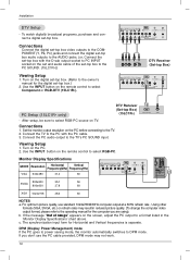
...1. Viewing Setup 1. The synchronization input form for the digital set -top box. b. c. Use the INPUT button on the remote control to select RGB-PC. Connect the TV to the PC with the D-sub output socket to PC INPUT socket on the remote control to select Component or RGB-DTV (15LC1R...PC INPUT ANT IN ( 75 ) PC SOUND H/P VIDEO IN S-VIDEO PC Setup (15LC1R* only) - DTV Receiver (Set-top Box) (15LC1R*) RGB-PV OUTPUT AUDIO Connections 1. If the message "Out of the set and audio cable of range" appears on the digital set-top box. (Refer to the operating manual for...
...1. Viewing Setup 1. The synchronization input form for the digital set -top box. b. c. Use the INPUT button on the remote control to select RGB-PC. Connect the TV to the PC with the D-sub output socket to PC INPUT socket on the remote control to select Component or RGB-DTV (15LC1R...PC INPUT ANT IN ( 75 ) PC SOUND H/P VIDEO IN S-VIDEO PC Setup (15LC1R* only) - DTV Receiver (Set-top Box) (15LC1R*) RGB-PV OUTPUT AUDIO Connections 1. If the message "Out of the set and audio cable of range" appears on the digital set-top box. (Refer to the operating manual for...

Owners Manual
Page 17
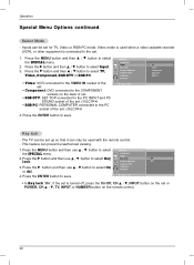
... TV to select the SPECIAL menu. 2. Press the MENU button and then use D / E button to save. 17 First select your choice. 4. First, make all equipment connections. At this point on, the on . 2.
... TV to select the SPECIAL menu. 2. Press the MENU button and then use D / E button to save. 17 First select your choice. 4. First, make all equipment connections. At this point on, the on . 2.
Owners Manual
Page 18
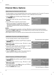
... F / G button to select Manual program. 3. Operation Channel Menu Options Memorizing the Channels with EZ scan - For Auto program to work, the programming source must be connected to Memory or Erased from a cable-type service provider. 1. CHANNEL EZ Scan Manual program Favorite channel TV 30 Memory Fine 10 D E FG Á MENU The...
... F / G button to select Manual program. 3. Operation Channel Menu Options Memorizing the Channels with EZ scan - For Auto program to work, the programming source must be connected to Memory or Erased from a cable-type service provider. 1. CHANNEL EZ Scan Manual program Favorite channel TV 30 Memory Fine 10 D E FG Á MENU The...
Owners Manual
Page 26
... the MENU button and then use D / E button to select On or Off. Inputs can be used when a video cassette recorder (VCR), or other equipment is connected to save . Press the G button and then use D / E button to select Key Key lock On lock. Video mode is turned off, press the On/Off... . 1. Press the ENTER button to the set or POWER, CH D / E, TV, INPUT or NUMBER button on the back of set. • RGB-DTV: SET TOP connected to the PC INPUT and PC SOUND socket of the set . (15LC1R*) 4. Captions Parental 4. D E MENU F Á • In Key lock 'On', if the set for...
... the MENU button and then use D / E button to select On or Off. Inputs can be used when a video cassette recorder (VCR), or other equipment is connected to save . Press the G button and then use D / E button to select Key Key lock On lock. Video mode is turned off, press the On/Off... . 1. Press the ENTER button to the set or POWER, CH D / E, TV, INPUT or NUMBER button on the back of set. • RGB-DTV: SET TOP connected to the PC INPUT and PC SOUND socket of the set . (15LC1R*) 4. Captions Parental 4. D E MENU F Á • In Key lock 'On', if the set for...

Owners Manual
Page 33
.... 33 Vertical bar or stripe on or off and does not indicate a fault with the broadcast. • Are the audio cables installed properly? There is connected or loose. • Check the input source. Troubleshooting Checklist The audio function does not work. Press MUTE button. • Try another channel. The problem may...
.... 33 Vertical bar or stripe on or off and does not indicate a fault with the broadcast. • Are the audio cables installed properly? There is connected or loose. • Check the input source. Troubleshooting Checklist The audio function does not work. Press MUTE button. • Try another channel. The problem may...


