
Service Guide
Page 3
... 2-17 SSA Maintenance Analysis Procedures (MAPs 2-35 MAP 2010: SSA Hot-Swap Disk Drive-Start 2-37 Chapter 3. Error Code to FRU Index 3-1 Firmware/POST Error Codes 3-2 Bus SRN to FRU Reference Table 3-27 Checkpoints 3-29 Location Codes 3-46 Preface iii Contents Communications Statements vii Federal Communications Commission (FCC) Statement vii International Electrotechnical Commission (IEC) Statement...
... 2-17 SSA Maintenance Analysis Procedures (MAPs 2-35 MAP 2010: SSA Hot-Swap Disk Drive-Start 2-37 Chapter 3. Error Code to FRU Index 3-1 Firmware/POST Error Codes 3-2 Bus SRN to FRU Reference Table 3-27 Checkpoints 3-29 Location Codes 3-46 Preface iii Contents Communications Statements vii Federal Communications Commission (FCC) Statement vii International Electrotechnical Commission (IEC) Statement...
Service Guide
Page 4
... Diagnostics 4-1 Chapter 5. System Management Services 5-1 Graphical System Management Services 5-1 Config 5-5 MultiBoot 5-7 Utilities 5-10 Password 5-12 Error Log 5-16 RIPL 5-17 SCSI ID 5-21 Update 5-22 Text-Based System Management Services 5-24 Chapter 6. Removal and Replacement...45 Serial/Parallel Card 6-46 iv Service Guide Physical Location Codes AIX and Physical Location Code Reference Table AIX Location Codes SSA Location Code Format SSA Loops and Links SSA Service Aids Service Aid Error Codes Using the Service Aids for SSA-Link Problem Determination Finding ...
... Diagnostics 4-1 Chapter 5. System Management Services 5-1 Graphical System Management Services 5-1 Config 5-5 MultiBoot 5-7 Utilities 5-10 Password 5-12 Error Log 5-16 RIPL 5-17 SCSI ID 5-21 Update 5-22 Text-Based System Management Services 5-24 Chapter 6. Removal and Replacement...45 Serial/Parallel Card 6-46 iv Service Guide Physical Location Codes AIX and Physical Location Code Reference Table AIX Location Codes SSA Location Code Format SSA Loops and Links SSA Service Aids Service Aid Error Codes Using the Service Aids for SSA-Link Problem Determination Finding ...

Service Guide
Page 15
...Hardware Planning Information contains information to help users set up, install options, configure, modify, and solve minor problems. The IBM RS/6000 Diagnostic Information for Multiple Bus Systems contains information about adapters, external devices, and cabling. It also contains Maintenance ... and manufacturing of this product. Preface xv The IBM RS/6000 Adapter, Device, and Cable Information for Multiple Bus Systems contains common diagnostic procedures, error codes, service request numbers, and failing function codes. About This Book This book provides maintenance information ...
...Hardware Planning Information contains information to help users set up, install options, configure, modify, and solve minor problems. The IBM RS/6000 Diagnostic Information for Multiple Bus Systems contains information about adapters, external devices, and cabling. It also contains Maintenance ... and manufacturing of this product. Preface xv The IBM RS/6000 Adapter, Device, and Cable Information for Multiple Bus Systems contains common diagnostic procedures, error codes, service request numbers, and failing function codes. About This Book This book provides maintenance information ...
Service Guide
Page 25
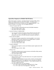
...1-9 The CPU compatibility test is not present, the LCD displays 4BA00001. 1. The user can enter the Service Processor menus whenever the LCD code is pressed. Service Processor Self Test Service Processor card performs self test and NVRAM initialization. E0E1. 4. Device Configuration and Test System firmware ...performs a simple test on the Central Electronics Complex (CEC) chips when the POWER Button is "OK", "STBY", or has an eight digit error code on an ASCII terminal connected to start the On-line Diagnostics (Hard Disk) Chapter 1. The VPD data is read and the CRC is ...
...1-9 The CPU compatibility test is not present, the LCD displays 4BA00001. 1. The user can enter the Service Processor menus whenever the LCD code is pressed. Service Processor Self Test Service Processor card performs self test and NVRAM initialization. E0E1. 4. Device Configuration and Test System firmware ...performs a simple test on the Central Electronics Complex (CEC) chips when the POWER Button is "OK", "STBY", or has an eight digit error code on an ASCII terminal connected to start the On-line Diagnostics (Hard Disk) Chapter 1. The VPD data is read and the CRC is ...

Service Guide
Page 32
...) is displayed on Go to the Fast Path MAP in the IBM RS/6000 Diagnostic Information for power on the system console. You have an 8-digit error code displayed. Go to FRU Index" on page 2-6. Go to Chapter 3, "Error Code to "MAP 1020: Problem Determination" on page 3-1. The system was...Symptom Analysis You have OK displayed The Service Processor (SP) is still powered on page 3-44. Record the error code. The term "POST indicators" refer to "MAP 410: Repair Checkout" in the IBM RS/6000 Diagnostic Information for possible operating system fault indications.
...) is displayed on Go to the Fast Path MAP in the IBM RS/6000 Diagnostic Information for power on the system console. You have an 8-digit error code displayed. Go to FRU Index" on page 2-6. Go to Chapter 3, "Error Code to "MAP 1020: Problem Determination" on page 3-1. The system was...Symptom Analysis You have OK displayed The Service Processor (SP) is still powered on page 3-44. Record the error code. The term "POST indicators" refer to "MAP 410: Repair Checkout" in the IBM RS/6000 Diagnostic Information for possible operating system fault indications.

Service Guide
Page 33
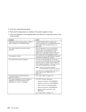
...notes on page 2-17. 1. If the problem is attached to a ASCII terminal, suspect the ASCII terminal. Go to the Fast Path MAP in the IBM RS/6000 Diagnostic Information for Multiple Bus Systems. Chapter 2. If you do not reveal a problem. 1. Go to "MAP 1540: Minimum Configuration" on...the Problem Determination Procedures for the display. 2. Make sure that the password is displayed when booting in the control panel followed by additional error codes. If problems persist, go to "MAP 1540: Minimum Configuration" on the system console, and the operator panel is connected to S1....
...notes on page 2-17. 1. If the problem is attached to a ASCII terminal, suspect the ASCII terminal. Go to the Fast Path MAP in the IBM RS/6000 Diagnostic Information for Multiple Bus Systems. Chapter 2. If you do not reveal a problem. 1. Go to "MAP 1540: Minimum Configuration" on...the Problem Determination Procedures for the display. 2. Make sure that the password is displayed when booting in the control panel followed by additional error codes. If problems persist, go to "MAP 1540: Minimum Configuration" on the system console, and the operator panel is connected to S1....

Service Guide
Page 34
...attached to the SCSI bus, it may be in conflict: 1. Go to the Fast Path MAP in the IBM RS/6000 Diagnostic Information for Multiple Bus Systems. Note: If the operator panel displays 2 sets of numbers,... If settings do not appear to be set to use the same SCSI bus ID as the error code. Action If the number displayed begins with the System Management Services. or "E1xx-EFFF" then ...the four-digit number displayed in the operator panel, then go to the Fast Path MAP in the IBM RS/6000 Diagnostic Information for Multiple Bus Systems. 2-4 Service Guide The power light does not come on...
...attached to the SCSI bus, it may be in conflict: 1. Go to the Fast Path MAP in the IBM RS/6000 Diagnostic Information for Multiple Bus Systems. Note: If the operator panel displays 2 sets of numbers,... If settings do not appear to be set to use the same SCSI bus ID as the error code. Action If the number displayed begins with the System Management Services. or "E1xx-EFFF" then ...the four-digit number displayed in the operator panel, then go to the Fast Path MAP in the IBM RS/6000 Diagnostic Information for Multiple Bus Systems. 2-4 Service Guide The power light does not come on...
Service Guide
Page 36
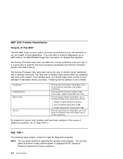
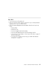
...Menu, go to MAP 0020 in the IBM RS/6000 Diagnostic Information for restoration before proceeding (see Service Processor System Information Menu). You are also asked questions regarding the operator panel display. Enable supplemental restart policy to examine that error log before you leave. It is a... and disable call-out on displayed POST indicators. MAP 1020: Problem Determination Purpose of This MAP Use this MAP to get an error code if you were not provided one or more symptoms in the course of analyzing a problem. From the Service Processor System Power Control...
...Menu, go to MAP 0020 in the IBM RS/6000 Diagnostic Information for restoration before proceeding (see Service Processor System Information Menu). You are also asked questions regarding the operator panel display. Enable supplemental restart policy to examine that error log before you leave. It is a... and disable call-out on displayed POST indicators. MAP 1020: Problem Determination Purpose of This MAP Use this MAP to get an error code if you were not provided one or more symptoms in the course of analyzing a problem. From the Service Processor System Power Control...
Service Guide
Page 38
... The system stopped and a POST indicator is displayed on the system console and an eight-digit error code is displayed on the operator panel. network, record error code M0NET000. speaker (audio), record error code M0BT0000. Find your symptom in the Action column. then follow the instructions given in the following ...the beginning of the other conditions to continue until a correct password has been entered. When you pressed the correct key in the IBM RS/6000 Diagnostic Information for the flash EPROM should be executed. The system login prompt is displayed. 5. If you are sure you...
... The system stopped and a POST indicator is displayed on the system console and an eight-digit error code is displayed on the operator panel. network, record error code M0NET000. speaker (audio), record error code M0BT0000. Find your symptom in the Action column. then follow the instructions given in the following ...the beginning of the other conditions to continue until a correct password has been entered. When you pressed the correct key in the IBM RS/6000 Diagnostic Information for the flash EPROM should be executed. The system login prompt is displayed. 5. If you are sure you...

Service Guide
Page 39
.... Maintenance Analysis Procedures 2-9 Symptom The system stops and a 4-digit number is the last three digits of numbers as the error code. or "E1xx-EFFF" then go to the Fast Path MAP in the IBM RS/6000 Diagnostic Information for Multiple Bus Systems. Note: If the operator panel displays 2 sets of numbers, use the...
.... Maintenance Analysis Procedures 2-9 Symptom The system stops and a 4-digit number is the last three digits of numbers as the error code. or "E1xx-EFFF" then go to the Fast Path MAP in the IBM RS/6000 Diagnostic Information for Multiple Bus Systems. Note: If the operator panel displays 2 sets of numbers, use the...
Service Guide
Page 40
... (W.T.). Note: If the eight-digit error code is not listed in Chapter 3, "Error Code to FRU Index" on page 3-1. then go to "Step 1020-3." Find the eight-digit error code in the Action column. then follow the instructions given in Chapter 3, "Error Code to FRU Index," look for this type... of the Enter key. Identify by the Japanese characters.) ASCII terminal keyboard Action Record error code M0KBD001; Record error code M0KBD002; Go to "Step 1020-3." The Enter key extends into two horizontal rows. Perform the action listed. 2-10 Service...
... (W.T.). Note: If the eight-digit error code is not listed in Chapter 3, "Error Code to FRU Index" on page 3-1. then go to "Step 1020-3." Find the eight-digit error code in the Action column. then follow the instructions given in Chapter 3, "Error Code to FRU Index," look for this type... of the Enter key. Identify by the Japanese characters.) ASCII terminal keyboard Action Record error code M0KBD001; Record error code M0KBD002; Go to "Step 1020-3." The Enter key extends into two horizontal rows. Perform the action listed. 2-10 Service...
Service Guide
Page 41
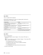
... attached keyboard or the 1 key on the system unit. 2. Maintenance Analysis Procedures 2-11 If the error was logged during the current boot attempt, record it. Choose Utilities Choose Error Log If an error is logged in the Chapter 3, "Error Code to "MAP 1540: Minimum Configuration" on page 3-1 and do the listed action. Chapter 2. Look up...
... attached keyboard or the 1 key on the system unit. 2. Maintenance Analysis Procedures 2-11 If the error was logged during the current boot attempt, record it. Choose Utilities Choose Error Log If an error is logged in the Chapter 3, "Error Code to "MAP 1540: Minimum Configuration" on page 3-1 and do the listed action. Chapter 2. Look up...

Service Guide
Page 73
... a location code. Chapter 3. Error Code to FRU Index The Error Code to FRU Index 3-1 Notes: 1. If you decide which device generated the error. See "Location Codes" on page 2-11 to enable system startup. Also check to ensure that any client or server that the client IP addresses used by the server can be changed in the IBM RS...
... a location code. Chapter 3. Error Code to FRU Index The Error Code to FRU Index 3-1 Notes: 1. If you decide which device generated the error. See "Location Codes" on page 2-11 to enable system startup. Also check to ensure that any client or server that the client IP addresses used by the server can be changed in the IBM RS...

Service Guide
Page 74
... to "MAP 410: Repair Checkout" in the IBM RS/6000 Diagnostic Information for general considerations. 2. Change IP address. Turn off then on device, no error/location code information available. Have network administrator verify the server configuration for this client. The location code (if present) in the error log entry should identify the location of 24...
... to "MAP 410: Repair Checkout" in the IBM RS/6000 Diagnostic Information for general considerations. 2. Change IP address. Turn off then on device, no error/location code information available. Have network administrator verify the server configuration for this client. The location code (if present) in the error log entry should identify the location of 24...
Service Guide
Page 75
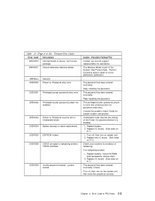
...tampering evident, CMOS initialized. 20E00009 Invalid password entered - Replace I /O board. (See notes on 3-1.) Check your machine for assistance. Error Code to FRU Index 3-3 Chapter 3. Consult the system's User's Guide for password initial entry. Replace battery. 2. The Machine Model is ...for jumper location and position. The privileged-access password jumper is part of tampering. Retry installing the password. Firmware Error Codes. Action / Possible Failing FRU Contact you service support representative for evidence of the System Vital Product Data. Replace ...
...tampering evident, CMOS initialized. 20E00009 Invalid password entered - Replace I /O board. (See notes on 3-1.) Check your machine for assistance. Error Code to FRU Index 3-3 Chapter 3. Consult the system's User's Guide for password initial entry. Replace battery. 2. The Machine Model is ...for jumper location and position. The privileged-access password jumper is part of tampering. Retry installing the password. Firmware Error Codes. Action / Possible Failing FRU Contact you service support representative for evidence of the System Vital Product Data. Replace ...

Service Guide
Page 76
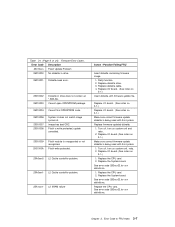
... Turn off , turn on system unit. 2. Enter valid IP parameter. Replace I /O board, (See notes on 3-1.) 3. Error Code Description 20E0000A EEPROM lock problem. 20E0000B EEPROM write problem 20E0000C EEPROM read problem. 20E00017 20EE0xxx 20EE0003 Cold boot needed for jumper location ...unit. 2. replace the I /O board. (See notes on 3-1.) 1. Replace the device or adapter. 2. Replace System Board. 3-4 Service Guide Firmware Error Codes. Replace I /O board. (See notes on 3-1.) 1. Replace I /O board should always have (at least) 2 integrated PCI SCSI controllers; Example:...
... Turn off , turn on system unit. 2. Enter valid IP parameter. Replace I /O board, (See notes on 3-1.) 3. Error Code Description 20E0000A EEPROM lock problem. 20E0000B EEPROM write problem 20E0000C EEPROM read problem. 20E00017 20EE0xxx 20EE0003 Cold boot needed for jumper location ...unit. 2. replace the I /O board. (See notes on 3-1.) 1. Replace the device or adapter. 2. Replace System Board. 3-4 Service Guide Firmware Error Codes. Replace I /O board. (See notes on 3-1.) 1. Replace I /O board should always have (at least) 2 integrated PCI SCSI controllers; Example:...

Service Guide
Page 77
...known to have a copy of the Operating System as boot list) to include devices that are known to the location of the battery). Firmware Error Codes. Action / Possible Failing FRU Values normally found in non-volatile storage that point to contain a copy of the Operating System. This can ... The system was not able to find an operating system on the device list that caused the system to the operating system found . Error Code Description 20EE000A Pointer to lose non-volatile storage information (drainage or replacement of an Operating System were not found in the default boot list...
...known to have a copy of the Operating System as boot list) to include devices that are known to the location of the battery). Firmware Error Codes. Action / Possible Failing FRU Values normally found in non-volatile storage that point to contain a copy of the Operating System. This can ... The system was not able to find an operating system on the device list that caused the system to the operating system found . Error Code Description 20EE000A Pointer to lose non-volatile storage information (drainage or replacement of an Operating System were not found in the default boot list...

Service Guide
Page 78
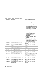
...Replace the SCSI device. 2. Refer to 21A00xxx for a description and repair action for the xxx value. Refer to the notes in error code 21A000xxx. 1. Ensure SCSI bus is assigned a unique SCSI ID. Refer to 21A00xxx for a description and repair action for the xxx...the controller and each device on the SCSI bus is properly terminated. Replace the SCSI device. Firmware Error Codes. Refer to the notes in error code 21A000xxx. Replace the System Board. hardware error. 21A00002 Test Unit Ready Failed - Replace the SCSI controller. Table 3-1 (Page 5 of the controller...
...Replace the SCSI device. 2. Refer to 21A00xxx for a description and repair action for the xxx value. Refer to the notes in error code 21A000xxx. 1. Ensure SCSI bus is assigned a unique SCSI ID. Refer to 21A00xxx for a description and repair action for the xxx...the controller and each device on the SCSI bus is properly terminated. Replace the SCSI device. Firmware Error Codes. Refer to the notes in error code 21A000xxx. Replace the System Board. hardware error. 21A00002 Test Unit Ready Failed - Replace the SCSI controller. Table 3-1 (Page 5 of the controller...
Service Guide
Page 79
...See notes on 3-1.) Replace I /O board. (See notes on 3-1.) Make sure correct firmware update diskette is being used with firmware update file. Firmware Error Codes. Replace diskette cable. 4. Replace I /O board. (See notes on 3-1.) Insert diskette with this system. 1. Turn off , turn on 3-1.) ...module is being used with this system. Replace I /O board. (See notes on system unit, retry. 2. See error code 2B2xxx22 for xxx definitions. See error code 2B2xxx22 for xxx definitions. Replace diskette drive. 3. Replace firmware updated diskette. 1. Turn off , turn on 3-1.) ...
...See notes on 3-1.) Replace I /O board. (See notes on 3-1.) Make sure correct firmware update diskette is being used with firmware update file. Firmware Error Codes. Replace diskette cable. 4. Replace I /O board. (See notes on 3-1.) Insert diskette with this system. 1. Turn off , turn on 3-1.) ...module is being used with this system. Replace I /O board. (See notes on system unit, retry. 2. See error code 2B2xxx22 for xxx definitions. See error code 2B2xxx22 for xxx definitions. Replace diskette drive. 3. Replace firmware updated diskette. 1. Turn off , turn on 3-1.) ...
Service Guide
Page 80
... battery. 3. Refer to expand target partition while writing VPD data. When one of the 25A80000 error, these errors occurs, any system customization (eg. Unable to Action under error code 25A80xxx. Turn off, turn on 3-1.) Refer to Action under error code 25A80xxx. Error Code Description 25A80xxx NVRAM problems 25A80000 Initialization failed, device test failed. 25A80001 25A80002 25A80011 25A80012 25A80100...
... battery. 3. Refer to expand target partition while writing VPD data. When one of the 25A80000 error, these errors occurs, any system customization (eg. Unable to Action under error code 25A80xxx. Turn off, turn on 3-1.) Refer to Action under error code 25A80xxx. Error Code Description 25A80xxx NVRAM problems 25A80000 Initialization failed, device test failed. 25A80001 25A80002 25A80011 25A80012 25A80100...


