
Service Guide
Page 21
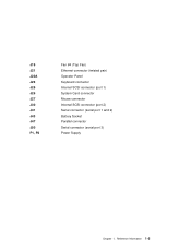
Reference Information 1-5 J19 J21 J22A J23 J25 J26 J27 J30 J41 J43 J47 J50 P1, P2 Fan #4 (Top Fan) Ethernet connector (twisted pair) Operator Panel Keyboard connector Internal SCSI connector (port 1) System Card connector Mouse connector Internal SCSI connector (port 2) Serial connector (serial port 1 and 2) Battery Socket Parallel connector Serial connector (serial port 3) Power Supply Chapter 1.
Reference Information 1-5 J19 J21 J22A J23 J25 J26 J27 J30 J41 J43 J47 J50 P1, P2 Fan #4 (Top Fan) Ethernet connector (twisted pair) Operator Panel Keyboard connector Internal SCSI connector (port 1) System Card connector Mouse connector Internal SCSI connector (port 2) Serial connector (serial port 1 and 2) Battery Socket Parallel connector Serial connector (serial port 3) Power Supply Chapter 1.
Service Guide
Page 25
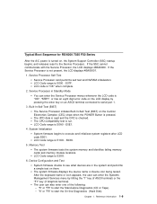
... an eight digit error code on the LCD display by hitting the "1" key (if ASCII terminal) or the "F1" key (if Graphics terminal). After the keyboard name or icon appears, the user can also enter one of the following: - E07F. The VPD data is read and the CRC is E000 - E0E1...
... an eight digit error code on the LCD display by hitting the "1" key (if ASCII terminal) or the "F1" key (if Graphics terminal). After the keyboard name or icon appears, the user can also enter one of the following: - E07F. The VPD data is read and the CRC is E000 - E0E1...

Service Guide
Page 33
...Path MAP in service mode. If so, then the keyboard or its controller may be faulty. 1. If entering the password from a keyboard which is blank. If entering the password from the keyboard which is displayed when booting in the IBM RS/6000 Diagnostic Information for the terminal. If you ...do not find a problem then replace the display adapter. 3. Symptom The system does not respond to the password being entered from the ASCII terminal or keyboard defined as...
...Path MAP in service mode. If so, then the keyboard or its controller may be faulty. 1. If entering the password from a keyboard which is blank. If entering the password from the keyboard which is displayed when booting in the IBM RS/6000 Diagnostic Information for the terminal. If you ...do not find a problem then replace the display adapter. 3. Symptom The system does not respond to the password being entered from the ASCII terminal or keyboard defined as...
Service Guide
Page 37
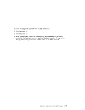
Turn the power off. 3. Turn the power on an ASCII terminal. 1. Maintenance Analysis Procedures 2-7 Insert the diagnostic CD-ROM into the CD-ROM drive. 2. Chapter 2. When the keyboard indicator is displayed (the word keyboard on an ASCII terminal or the keyboard icon on a graphical display), press the F5 key on the directly-attached keyboard or the number 5 key on . 4.
Turn the power off. 3. Turn the power on an ASCII terminal. 1. Maintenance Analysis Procedures 2-7 Insert the diagnostic CD-ROM into the CD-ROM drive. 2. Chapter 2. When the keyboard indicator is displayed (the word keyboard on an ASCII terminal or the keyboard icon on a graphical display), press the F5 key on the directly-attached keyboard or the number 5 key on . 4.
Service Guide
Page 38
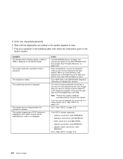
...you pressed the correct key in a timely manner, go to "Step 1020-2" on the operator panel. Go to MAP 0020 in the IBM RS/6000 Diagnostic Information for Multiple Bus Systems. You may not have pressed the correct key or you may not have entered a valid ...page 2-10. 2-8 Service Guide Enter the password. SCSI, record error code M0CON000. If the POST indicator represents: memory, record error code M0MEM002. keyboard, record error code M0KBD000. Action The flash EPROM data is not displayed. then follow the instructions given in the following table; The diagnostics loaded. network...
...you pressed the correct key in a timely manner, go to "Step 1020-2" on the operator panel. Go to MAP 0020 in the IBM RS/6000 Diagnostic Information for Multiple Bus Systems. You may not have pressed the correct key or you may not have entered a valid ...page 2-10. 2-8 Service Guide Enter the password. SCSI, record error code M0CON000. If the POST indicator represents: memory, record error code M0MEM002. keyboard, record error code M0KBD000. Action The flash EPROM data is not displayed. then follow the instructions given in the following table; The diagnostics loaded. network...
Service Guide
Page 40
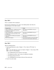
...key is in the following table; Type 102 keyboard (W.T.). then go to "Step 1020-3." Keyboard Type Type 101 keyboard (U.S.). Note: If the eight-digit error code is a problem with the keyboard. The Enter key extends into two horizontal rows. Type 106 keyboard. (Identify by the size of the Enter key.... Perform the action listed. 2-10 Service Guide Identify by the Japanese characters.) ASCII terminal keyboard Action Record error code M0KBD001; Record error code M0KBD003; Step 1020-3 Take the following : Any supplemental service manual for ...
...key is in the following table; Type 102 keyboard (W.T.). then go to "Step 1020-3." Keyboard Type Type 101 keyboard (U.S.). Note: If the eight-digit error code is a problem with the keyboard. The Enter key extends into two horizontal rows. Type 106 keyboard. (Identify by the size of the Enter key.... Perform the action listed. 2-10 Service Guide Identify by the Japanese characters.) ASCII terminal keyboard Action Record error code M0KBD001; Record error code M0KBD003; Step 1020-3 Take the following : Any supplemental service manual for ...
Service Guide
Page 41
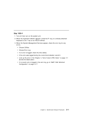
... do the listed action. Look up the error in the error log, go to FRU Index" on page 2-17. When the keyboard indicator appears, press the F1 key on a directly attached keyboard or the 1 key on the system unit. 2. If no recent error is logged, check the time stamp. Maintenance Analysis Procedures...
... do the listed action. Look up the error in the error log, go to FRU Index" on page 2-17. When the keyboard indicator appears, press the F1 key on a directly attached keyboard or the 1 key on the system unit. 2. If no recent error is logged, check the time stamp. Maintenance Analysis Procedures...
Service Guide
Page 48
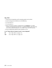
.... 6. Ensure that the diagnostics and the operating system are shut down. 2. When the keyboard indicator is displayed (the word keyboard on an ASCII terminal or the keyboard and hand icon on a graphical display), press the F5 key on the directly-attached keyboard or the number 5 key on page 2-31. 2-18 Service Guide Turn the...
.... 6. Ensure that the diagnostics and the operating system are shut down. 2. When the keyboard indicator is displayed (the word keyboard on an ASCII terminal or the keyboard and hand icon on a graphical display), press the F5 key on the directly-attached keyboard or the number 5 key on page 2-31. 2-18 Service Guide Turn the...

Service Guide
Page 54
... so. 7. Enter the appropriate password when prompted to the I/O planar. Wait until the SMS screen is displayed, press the F1 key on the directly attached keyboard or the number 1 key on the rear of the system unit. 3. Step 1540-7 1. Turn the power on the rear of the system unit. If an... ASCII terminal has been defined as the system console, install the display adapter and connect the display to stop. 2-24 Service Guide When the keyboard indicator is displayed or the system appears to it. Turn the power off. 2. Reconnect the system console. Plug the...
... so. 7. Enter the appropriate password when prompted to the I/O planar. Wait until the SMS screen is displayed, press the F1 key on the directly attached keyboard or the number 1 key on the rear of the system unit. 3. Step 1540-7 1. Turn the power on the rear of the system unit. If an... ASCII terminal has been defined as the system console, install the display adapter and connect the display to stop. 2-24 Service Guide When the keyboard indicator is displayed or the system appears to it. Turn the power off. 2. Reconnect the system console. Plug the...
Service Guide
Page 56
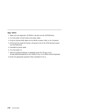
... SCSI cable into the CD-ROM drive. 2. Enter the appropriate password when prompted to do so. 2-26 Service Guide Reinstall the power cable. 6. After the keyboard indicator is inserted into the SCSI connector (J25) on . 7. Make sure the diagnostic CD-ROM is displayed, press the F5 key on the directly-attached...
... SCSI cable into the CD-ROM drive. 2. Enter the appropriate password when prompted to do so. 2-26 Service Guide Reinstall the power cable. 6. After the keyboard indicator is inserted into the SCSI connector (J25) on . 7. Make sure the diagnostic CD-ROM is displayed, press the F5 key on the directly-attached...
Service Guide
Page 58
...page 2-29. 2-28 Service Guide Diskette drive cable 3. YES Go to do not find a problem return to "Step 1540-1" on an ASCII terminal keyboard. 7. Step 1540-9 The system is identified or all the FRUs have not been exchanged. 1. Reinstall the power cable. 5. Diskette drive 2. If ..., call your service support person for the new symptom. I /O planar. 4. Turn the power off and remove the power cable. 3. After the keyboard indicator is inserted into the diskette drive connector on the I /O planar (see notes on . 6. Make sure the diagnostic CD-ROM is displayed, ...
...page 2-29. 2-28 Service Guide Diskette drive cable 3. YES Go to do not find a problem return to "Step 1540-1" on an ASCII terminal keyboard. 7. Step 1540-9 The system is identified or all the FRUs have not been exchanged. 1. Reinstall the power cable. 5. Diskette drive 2. If ..., call your service support person for the new symptom. I /O planar. 4. Turn the power off and remove the power cable. 3. After the keyboard indicator is inserted into the diskette drive connector on the I /O planar (see notes on . 6. Make sure the diagnostic CD-ROM is displayed, ...
Service Guide
Page 59
... 4. Make sure the diagnostic CD-ROM is working correctly with this step until all I /O Planar device (parallel port device, serial port device, keyboard or mouse) that had been removed and any cables and devices that you installed requires supplemental media use the Process Supplemental Media task to do... the F5 key on the directly-attached keyboard or the number 5 key on . 6. Step 1540-10 The system is inserted into the CD-ROM drive. 2. One of the FRUs (adapters) are installed, then go to "MAP 410: Repair Checkout" in the IBM RS/6000 Diagnostic Information for Multiple Bus ...
... 4. Make sure the diagnostic CD-ROM is working correctly with this step until all I /O Planar device (parallel port device, serial port device, keyboard or mouse) that had been removed and any cables and devices that you installed requires supplemental media use the Process Supplemental Media task to do... the F5 key on the directly-attached keyboard or the number 5 key on . 6. Step 1540-10 The system is inserted into the CD-ROM drive. 2. One of the FRUs (adapters) are installed, then go to "MAP 410: Repair Checkout" in the IBM RS/6000 Diagnostic Information for Multiple Bus ...

Service Guide
Page 60
... adapter, disconnect one installed) 2. After the keyboard indicator appears, press the F5 key on the directly-attached keyboard or the number 5 key on page 2-1. 3. I/O planar If the I/O planar or a network adapter is replaced, see notes on an ASCII terminal keyboard. 8. If the symptom did not change and... all the FRUs have been disconnected. Exchange the defective device or cable. Go to "MAP 410: Repair Checkout" in the IBM RS/6000 Diagnostic Information for the new symptom. NO ...
... adapter, disconnect one installed) 2. After the keyboard indicator appears, press the F5 key on the directly-attached keyboard or the number 5 key on page 2-1. 3. I/O planar If the I/O planar or a network adapter is replaced, see notes on an ASCII terminal keyboard. 8. If the symptom did not change and... all the FRUs have been disconnected. Exchange the defective device or cable. Go to "MAP 410: Repair Checkout" in the IBM RS/6000 Diagnostic Information for the new symptom. NO ...

Service Guide
Page 76
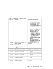
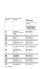
... requires 3 dots "." 20EE0004 Invalid IP parameter. 20EE0005 Invalid IP parameter (>255) 20EE0006 No SCSI controllers present 20EE0007 Keyboard not found 20EE0008 No configurable adapters found in correct position? Consult the system's User's Guide for password entry. Turn...off , turn on 3-1.) 1. Replace System Board. 3-4 Service Guide Example: 000.000.000.000 Enter valid (numeric) IP parameter in keyboard. 2. Error Code Description 20E0000A EEPROM lock problem. 20E0000B EEPROM write problem 20E0000C EEPROM read problem. 20E00017 20EE0xxx 20EE0003 Cold boot needed for ...
... requires 3 dots "." 20EE0004 Invalid IP parameter. 20EE0005 Invalid IP parameter (>255) 20EE0006 No SCSI controllers present 20EE0007 Keyboard not found 20EE0008 No configurable adapters found in correct position? Consult the system's User's Guide for password entry. Turn...off , turn on 3-1.) 1. Replace System Board. 3-4 Service Guide Example: 000.000.000.000 Enter valid (numeric) IP parameter in keyboard. 2. Error Code Description 20E0000A EEPROM lock problem. 20E0000B EEPROM write problem 20E0000C EEPROM read problem. 20E00017 20EE0xxx 20EE0003 Cold boot needed for ...
Service Guide
Page 83
... notes on 3-1.) 1. Error Code to Action under error code 28030xxx. Firmware Error Codes. Action / Possible Failing FRU 1. Keyboard 2. Bad time/date values 1. Keyboard/Mouse controller failed self-test. These errors are warnings that occur during normal system usage. Replace the I /O board. (...restore a Power On Password, use the Operating System facility. 2. Mouse 2. Set the time and date. 2. Keyboard not present/detected. 29A00004 Keyboard stuck key test failed. 29B00004 Mouse not present/detected. 2B200402 Unsupported Processor. When one of 24). If the ...
... notes on 3-1.) 1. Error Code to Action under error code 28030xxx. Firmware Error Codes. Action / Possible Failing FRU 1. Keyboard 2. Bad time/date values 1. Keyboard/Mouse controller failed self-test. These errors are warnings that occur during normal system usage. Replace the I /O board. (...restore a Power On Password, use the Operating System facility. 2. Mouse 2. Set the time and date. 2. Keyboard not present/detected. 29A00004 Keyboard stuck key test failed. 29B00004 Mouse not present/detected. 2B200402 Unsupported Processor. When one of 24). If the ...
Service Guide
Page 100
.../device (01-D1-00-00) Parallel port/device (01-R1) Serial ports (1-3)/device (01-S1 to 01-S3) Mouse port/device (01-K1-01-00) Keyboard port/device (01-K1-00-00) Device installed in I/O Slot 8I (01-01 or 01-02) Device installed in I/O Slot 9I (01-01 or 01...
.../device (01-D1-00-00) Parallel port/device (01-R1) Serial ports (1-3)/device (01-S1 to 01-S3) Mouse port/device (01-K1-01-00) Keyboard port/device (01-K1-00-00) Device installed in I/O Slot 8I (01-01 or 01-02) Device installed in I/O Slot 9I (01-01 or 01...
Service Guide
Page 108
... Boot Problems" on 3-29. Create lpt node. Probe for this client. Turn off then on 3-29. Have network administrator verify the server configuration for (ISA) keyboard. See the note on 3-29. Table 3-5 (Page 5 of checkpoint E1DE. Create audio node. See the note on 3-29. See the note on 3-29. See the...
... Boot Problems" on 3-29. Create lpt node. Probe for this client. Turn off then on 3-29. Have network administrator verify the server configuration for (ISA) keyboard. See the note on 3-29. Table 3-5 (Page 5 of checkpoint E1DE. Create audio node. See the note on 3-29. See the note on 3-29. See the...

Service Guide
Page 109
...console is attached but there is displayed on 3-1.) 2. If selection screen(s) can be set to FRU Index 3-37 If selecting the console with a keyboard attached to the keystroke: 1. Create ISA ethernet node. Create ISA interrupt controller (pic) node. Action/ Possible Failing FRU See the note on 3-29... SCSI byte device node (ST). See the note on 3-29. Create dma node. Create (* wildcard *) SCSI block device node (SD). If replacing the keyboard does not fix the problem, replace the I /O board if these procedures do not reveal a problem. Error Code to : 9600 Baud No Parity 8 Data...
...console is attached but there is displayed on 3-1.) 2. If selection screen(s) can be set to FRU Index 3-37 If selecting the console with a keyboard attached to the keystroke: 1. Create ISA ethernet node. Create ISA interrupt controller (pic) node. Action/ Possible Failing FRU See the note on 3-29... SCSI byte device node (ST). See the note on 3-29. Create dma node. Create (* wildcard *) SCSI block device node (SD). If replacing the keyboard does not fix the problem, replace the I /O board if these procedures do not reveal a problem. Error Code to : 9600 Baud No Parity 8 Data...
Service Guide
Page 118
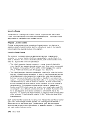
... planar (P1). A group of the one or two digits) that is located on the same physical package, but a different external connector. The keyboard controller and its connector (S1), which are produced by the system unit's firmware and AIX. In contrast, the location code P2-K1 actually points to...) separator character separates the base location code of the failing field replaceable units. Certain location types may also support secondary sub-locations, which is , the keyboard. For example, P1-C1 is a CPU card (C1) plugged into a planar (P1), or P1-M1 is a memory card (M1) plugged into (...
... planar (P1). A group of the one or two digits) that is located on the same physical package, but a different external connector. The keyboard controller and its connector (S1), which are produced by the system unit's firmware and AIX. In contrast, the location code P2-K1 actually points to...) separator character separates the base location code of the failing field replaceable units. Certain location types may also support secondary sub-locations, which is , the keyboard. For example, P1-C1 is a CPU card (C1) plugged into a planar (P1), or P1-M1 is a memory card (M1) plugged into (...
Service Guide
Page 122
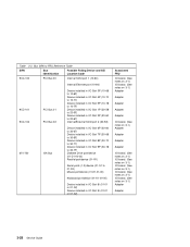
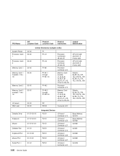
... Processor Card 1 Processor Card 2 Memory Card 1 Memory Card 1 moduleS 1 thru 16 Memory Card 2 Memory Card 2 moduleS 1 thru 16 I/O board FMC card Diskette Drive Keyboard Mouse Diskette Port Keyboard Port Mouse Port Serial Port 1 AIX Location Code Physical Location Code Physical Connection 00-00 00-00 00-00 00-00 00-00 00...
... Processor Card 1 Processor Card 2 Memory Card 1 Memory Card 1 moduleS 1 thru 16 Memory Card 2 Memory Card 2 moduleS 1 thru 16 I/O board FMC card Diskette Drive Keyboard Mouse Diskette Port Keyboard Port Mouse Port Serial Port 1 AIX Location Code Physical Location Code Physical Connection 00-00 00-00 00-00 00-00 00-00 00...

