
Service Guide
Page 25
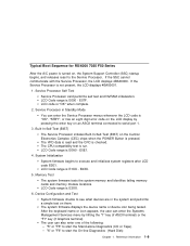
... Mode You can enter the Service Processor menus whenever the LCD code is run. Service Processor Self Test Service Processor card performs self test and NVRAM initialization. The CPU compatibility test is "OK", "STBY", or has an eight digit error code on the LCD display by hitting the "1" key (if ASCII terminal) or the "F1" key (if Graphics terminal). E2XX. 5. The system firmware displays the device name or device icon being tested. The user can enter the Systems Management Services menu...
... Mode You can enter the Service Processor menus whenever the LCD code is run. Service Processor Self Test Service Processor card performs self test and NVRAM initialization. The CPU compatibility test is "OK", "STBY", or has an eight digit error code on the LCD display by hitting the "1" key (if ASCII terminal) or the "F1" key (if Graphics terminal). E2XX. 5. The system firmware displays the device name or device icon being tested. The user can enter the Systems Management Services menu...
Service Guide
Page 31
... recovery instructions. If a network adapter, or the I/O planar is updated. Notes: 1. If recovery is captured in the IBM RS/6000 Diagnostic Information for licensed programs may need to perform. 1. In addition, the operating system configuration of the system is not possible, notify the system owner that the client IP addresses used by the server can assist you in fixing the problem. See "Location Codes" on the operator panel control assembly (connector...
... recovery instructions. If a network adapter, or the I/O planar is updated. Notes: 1. If recovery is captured in the IBM RS/6000 Diagnostic Information for licensed programs may need to perform. 1. In addition, the operating system configuration of the system is not possible, notify the system owner that the client IP addresses used by the server can assist you in fixing the problem. See "Location Codes" on the operator panel control assembly (connector...

Service Guide
Page 34
... the number displayed begins with the System Management Services. Reseat the operator panel cable. Operator Panel Control Assembly. Go to a controller/adapter than one . 2. Symptom The system stops and a 4-digit number is displayed in the IBM RS/6000 Diagnostic Information for Multiple Bus Systems. Note: If the operator panel displays 2 sets of numbers, use the same SCSI bus ID as the error code. The SMS configuration list or Boot sequence selection menu shows more than are displayed on page...
... the number displayed begins with the System Management Services. Reseat the operator panel cable. Operator Panel Control Assembly. Go to a controller/adapter than one . 2. Symptom The system stops and a 4-digit number is displayed in the IBM RS/6000 Diagnostic Information for Multiple Bus Systems. Note: If the operator panel displays 2 sets of numbers, use the same SCSI bus ID as the error code. The SMS configuration list or Boot sequence selection menu shows more than are displayed on page...
Service Guide
Page 36
... the Service Processor Setup Menu, go to No. Go to the Surveillance Setup Menu and disable surveillance. You are asked to record code numbers and use those numbers in its error log. Please be observant of analyzing a problem. Enable supplemental restart policy to the Serial Port Selection Menu and disable call-out on displayed POST indicators. Be prepared to perform certain actions based on both serial ports. From the Service Processor System Power Control Menu, disable unattended start mode...
... the Service Processor Setup Menu, go to No. Go to the Surveillance Setup Menu and disable surveillance. You are asked to record code numbers and use those numbers in its error log. Please be observant of analyzing a problem. Enable supplemental restart policy to the Serial Port Selection Menu and disable call-out on displayed POST indicators. Be prepared to perform certain actions based on both serial ports. From the Service Processor System Power Control Menu, disable unattended start mode...
Service Guide
Page 46
... do not find a problem, return to "Step 1520-1" on and the power LED come up, replace the memory card. SCSI devices, lowest bay to highest slot. 6. Connect the system unit power cable to highest slot. 5. If the symptom has changed, check for the new symptom. Step 1520-5 One of the parts that was just installed. Note: The memory DIMM pair must be installed in the power supply turn on page 2-13...
... do not find a problem, return to "Step 1520-1" on and the power LED come up, replace the memory card. SCSI devices, lowest bay to highest slot. 6. Connect the system unit power cable to highest slot. 5. If the symptom has changed, check for the new symptom. Step 1520-5 One of the parts that was just installed. Note: The memory DIMM pair must be installed in the power supply turn on page 2-13...
Service Guide
Page 47
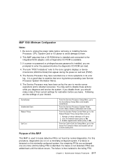
... error log. MAP 1540: Minimum Configuration Notes: 1. If a power-on a minimally-configured system. It is a good idea to examine that a CD-ROM drive is installed and connected to the integrated SCSI adapter, and a Diagnostics CD-ROM is used to locate defective FRUs not found by the user to monitor server operations and to the Surveillance Setup Menu and disable surveillance. From the Service Processor System Power Control Menu disable unattended start mode. The failure is detected on the minimally-configured...
... error log. MAP 1540: Minimum Configuration Notes: 1. If a power-on a minimally-configured system. It is a good idea to examine that a CD-ROM drive is installed and connected to the integrated SCSI adapter, and a Diagnostics CD-ROM is used to locate defective FRUs not found by the user to monitor server operations and to the Surveillance Setup Menu and disable surveillance. From the Service Processor System Power Control Menu disable unattended start mode. The failure is detected on the minimally-configured...

Service Guide
Page 54
... that a new console be selected. 5. Enter the appropriate password when prompted to the I/O planar. Turn the power off. 2. When the keyboard indicator is displayed or the system appears to the S1 connector on . 4. Wait until the SMS screen is displayed, press the F1 key on the directly attached keyboard or the number 1 key on the rear of the system unit. Also connect the internal serial and Ethernet cables to do...
... that a new console be selected. 5. Enter the appropriate password when prompted to the I/O planar. Turn the power off. 2. When the keyboard indicator is displayed or the system appears to the S1 connector on . 4. Wait until the SMS screen is displayed, press the F1 key on the directly attached keyboard or the number 1 key on the rear of the system unit. Also connect the internal serial and Ethernet cables to do...

Service Guide
Page 73
... otherwise indicated in the IBM RS/6000 Diagnostic Information for recovery instructions. Chapter 3. In addition, the operating system configuration of the network controller may be found under "Location Codes" on page 2-11 to the new one. Error Code to FRU Index The Error Code to FRU Index 3-1 Use this system is listed first. If you replace FRUs and the problem is corrected, go to "MAP 410: Repair Checkout" in the...
... otherwise indicated in the IBM RS/6000 Diagnostic Information for recovery instructions. Chapter 3. In addition, the operating system configuration of the network controller may be found under "Location Codes" on page 2-11 to the new one. Error Code to FRU Index The Error Code to FRU Index 3-1 Use this system is listed first. If you replace FRUs and the problem is corrected, go to "MAP 410: Repair Checkout" in the...

Service Guide
Page 74
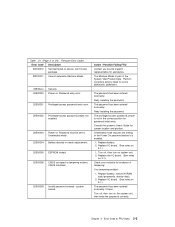
... table using code E174. Verify Boot List by other network device. 20A80002 Cannot get gateway IP address. 20A80003 Cannot get server hardware address. 20A80004 Bootp failed. 20A80005 20D00xxx 20D0000F File transmission (TFTP) failed. Have network administrator verify the server configuration for general considerations. 2. Unknown/Unrecognized device Self-test failed on page 3-44 for this error code. Refer to "MAP 410: Repair Checkout" in the IBM RS/6000 Diagnostic...
... table using code E174. Verify Boot List by other network device. 20A80002 Cannot get gateway IP address. 20A80003 Cannot get server hardware address. 20A80004 Bootp failed. 20A80005 20D00xxx 20D0000F File transmission (TFTP) failed. Have network administrator verify the server configuration for general considerations. 2. Unknown/Unrecognized device Self-test failed on page 3-44 for this error code. Refer to "MAP 410: Repair Checkout" in the IBM RS/6000 Diagnostic...
Service Guide
Page 75
Firmware Error Codes. The Machine Model is enabled. 1. Perform corrective actions listed for password initial entry. The privileged-access password jumper is not in the correct position for errors 2BA00050, 2BA00051. Consult the system's User's Guide for evidence of tampering. Turn off , then turn on Password must be set for assistance. Replace battery, restore NVRAM data (passwords, startup data). 2. Retry installing the password. Unattended mode requires the setting of the Power On password before it is part of 24). Replace the I/O board. (See...
Firmware Error Codes. The Machine Model is enabled. 1. Perform corrective actions listed for password initial entry. The privileged-access password jumper is not in the correct position for errors 2BA00050, 2BA00051. Consult the system's User's Guide for evidence of tampering. Turn off , then turn on Password must be set for assistance. Replace battery, restore NVRAM data (passwords, startup data). 2. Retry installing the password. Unattended mode requires the setting of the Power On password before it is part of 24). Replace the I/O board. (See...

Service Guide
Page 111
.... Error Code to composite image Erase flash Start O.B.E. Privileged-Access Password prompt. Diskette drive 3. See the note on 3-29. See the note on 3-29. Prompt should be executed. If a console is attached but nothing is displayed on it , go to the "Entry MAP" on page 2-1 with the symptom "All display problems." Chapter 3. See the note on 3-29. Determine boot device sequence. No boot image located. The...
.... Error Code to composite image Erase flash Start O.B.E. Privileged-Access Password prompt. Diskette drive 3. See the note on 3-29. See the note on 3-29. Prompt should be executed. If a console is attached but nothing is displayed on it , go to the "Entry MAP" on page 2-1 with the symptom "All display problems." Chapter 3. See the note on 3-29. Determine boot device sequence. No boot image located. The...

Service Guide
Page 114
... not stop at an E3xx code, skip to step 4 on page 3-43. Problem resolution steps: This section attempts to a specific Memory Card. Remove one of the Memory Card and instructions on module removal and installation (do not have to step 4 on page 3-43. 3-42 Service Guide Move the suspect bad tag from the installed Memory Card to the "Removal and Replacement Procedures" for "Memory Modules" on page 6-26 for...
... not stop at an E3xx code, skip to step 4 on page 3-43. Problem resolution steps: This section attempts to a specific Memory Card. Remove one of the Memory Card and instructions on module removal and installation (do not have to step 4 on page 3-43. 3-42 Service Guide Move the suspect bad tag from the installed Memory Card to the "Removal and Replacement Procedures" for "Memory Modules" on page 6-26 for...
Service Guide
Page 118
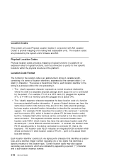
... same physical package, but may also support secondary sub-locations, which drives connector Z1, while location codes of the serial port 1 controller and its connector (S1), which is , the keyboard. Certain location types may require extended location information to ) the parent. The keyboard controller and its base location code), but a different external connector. Physical Location Codes Physical location codes provide a mapping of a function from any extended location information. The location codes are indicated by the standard dash...
... same physical package, but may also support secondary sub-locations, which drives connector Z1, while location codes of the serial port 1 controller and its connector (S1), which is , the keyboard. Certain location types may require extended location information to ) the parent. The keyboard controller and its base location code), but a different external connector. Physical Location Codes Physical location codes provide a mapping of a function from any extended location information. The location codes are indicated by the standard dash...

Service Guide
Page 165
... 3. Error Code to FRU Index 3-93 Abbreviations used in this section are: DRAM Dynamic random-access memory FRU Field-replaceable unit RAM Random-access memory ROM Read-only memory ROS Read-only storage SSA Serial storage architecture 4.5 GB, and 9.1 GB SSA Disk Drives Part number Disk drive module part number EC level Disk enclosure engineering change level Serial number Disk enclosure serial number Machine type and model Type and model Manufacturer Manufacturer and plant code ROS level and ID ROM and RAM code revision levels Device specific Z2 RAM code...
... 3. Error Code to FRU Index 3-93 Abbreviations used in this section are: DRAM Dynamic random-access memory FRU Field-replaceable unit RAM Random-access memory ROM Read-only memory ROS Read-only storage SSA Serial storage architecture 4.5 GB, and 9.1 GB SSA Disk Drives Part number Disk drive module part number EC level Disk enclosure engineering change level Serial number Disk enclosure serial number Machine type and model Type and model Manufacturer Manufacturer and plant code ROS level and ID ROM and RAM code revision levels Device specific Z2 RAM code...

Service Guide
Page 169
... changing device configurations. If you to set up adapters that are complete. System Management Services 5-1 If you can use this option if it is needed. Chapter 5. After the logo is used to use the graphical System Management Services described below. Chapter 5. Graphical System Management Services To start the Open Firmware command line or graphical System Management Services, turn on or restart the computer. The Open Firmware command line is displayed, initialization icons appear across the bottom of the screen...
... changing device configurations. If you to set up adapters that are complete. System Management Services 5-1 If you can use this option if it is needed. Chapter 5. After the logo is used to use the graphical System Management Services described below. Chapter 5. Graphical System Management Services To start the Open Firmware command line or graphical System Management Services, turn on or restart the computer. The Open Firmware command line is displayed, initialization icons appear across the bottom of the screen...

Service Guide
Page 171
... active console, view or clear the error log, and update your AIX documentation. Please see the explanation of the bootlist command in a particular hard disk. Chapter 5. In the case of AIX this would happen if the battery had been removed. System Management Services 5-3 To select a particular operating system as the default operating system To install from the list of possible devices To set and view the addresses...
... active console, view or clear the error log, and update your AIX documentation. Please see the explanation of the bootlist command in a particular hard disk. Chapter 5. In the case of AIX this would happen if the battery had been removed. System Management Services 5-3 To select a particular operating system as the default operating system To install from the list of possible devices To set and view the addresses...

Service Guide
Page 267
... be installed in Table Definition Backplane assembly The disk drive modules, blank disk drive modules, and internal SSA cables, are connected to your support center. The center can tell you whether you have a known problem and can, if necessary, provide you have been caused by a software error or by a microcode error. External SSA cable A cable that does not contain a disk drive module. Internal SSA cable Attaches the backplane to a carrier that plugs into...
... be installed in Table Definition Backplane assembly The disk drive modules, blank disk drive modules, and internal SSA cables, are connected to your support center. The center can tell you whether you have a known problem and can, if necessary, provide you have been caused by a software error or by a microcode error. External SSA cable A cable that does not contain a disk drive module. Internal SSA cable Attaches the backplane to a carrier that plugs into...
Service Guide
Page 296
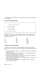
... telephone number of the maintenance provider's computer. The telephone number of the local system support provider's computer. The telephone number to which the server's modem is recommended. The Service Processor allows setting or changing telephone numbers for: Service Center Telephone Number: - Return to Previous Menu Serial port speed can be used to set for terminal performance or to accommodate modem capabilities. You may be set or change the telephone numbers for reporting a system failure. Serial Port Speed Setup Menu Serial Port Speed Setup Menu 1.
... telephone number of the maintenance provider's computer. The telephone number of the local system support provider's computer. The telephone number to which the server's modem is recommended. The Service Processor allows setting or changing telephone numbers for: Service Center Telephone Number: - Return to Previous Menu Serial port speed can be used to set for terminal performance or to accommodate modem capabilities. You may be set or change the telephone numbers for reporting a system failure. Serial Port Speed Setup Menu Serial Port Speed Setup Menu 1.
Service Guide
Page 348
... configuration Map 2-17 power MAP 2-12 problem determination MAP 2-6 maintenance, microcode 3-92 manufacturer and plant code 3-93 MAPs (maintenance analysis procedures) starting 2-37 using 2-35 memory bits 3-26 memory card locations 1-6 memory hang memory module removal and replacement 6-29 menu inactivity B-3 menus Certify Disk service aid 3-81 Configuration Verification service aid 3-77 Format Disk service aid 3-79 Function Select 3-65 general user B-4 Link Verification service aid 3-73 privileged user B-6 service processor B-3 service processor call-in/call-out setup B-16 service processor...
... configuration Map 2-17 power MAP 2-12 problem determination MAP 2-6 maintenance, microcode 3-92 manufacturer and plant code 3-93 MAPs (maintenance analysis procedures) starting 2-37 using 2-35 memory bits 3-26 memory card locations 1-6 memory hang memory module removal and replacement 6-29 menu inactivity B-3 menus Certify Disk service aid 3-81 Configuration Verification service aid 3-77 Format Disk service aid 3-79 Function Select 3-65 general user B-4 Link Verification service aid 3-73 privileged user B-6 service processor B-3 service processor call-in/call-out setup B-16 service processor...
Service Guide
Page 351
... language selection B-15 menu inactivity B-3 privileged user B-6 reboot policy B-23 restart policy B-23 serial port selection B-17 serial port speed setup B-18 service processor menus (continued) setup menu B-8 supported menu options B-2 system information B-13 system power control B-12 telephone number B-18 service processor setup C-1 service processor setup checklist C-1 service processor test C-1 service provider B-19 service request numbers (SRNs) description of A-3 software and microcode errors A-5 table A-6 Set Service Mode service aid 3-67 software and microcode errors A-5 sp checklist...
... language selection B-15 menu inactivity B-3 privileged user B-6 reboot policy B-23 restart policy B-23 serial port selection B-17 serial port speed setup B-18 service processor menus (continued) setup menu B-8 supported menu options B-2 system information B-13 system power control B-12 telephone number B-18 service processor setup C-1 service processor setup checklist C-1 service processor test C-1 service provider B-19 service request numbers (SRNs) description of A-3 software and microcode errors A-5 table A-6 Set Service Mode service aid 3-67 software and microcode errors A-5 sp checklist...


