
Service Guide
Page 3
... Safety Requirements vii European Union (EU) Statement viii Avis de conformité aux normes du ministère des Communications du Canada . Reference Information 1-1 System Unit Locations 1-1 System Data Flow 1-8 Typical Boot Sequence for Germany ix European Union (EU) Statement x VCCI Statement x Safety Notices xi Electrical Safety xi Laser Safety Information xiii...
... Safety Requirements vii European Union (EU) Statement viii Avis de conformité aux normes du ministère des Communications du Canada . Reference Information 1-1 System Unit Locations 1-1 System Data Flow 1-8 Typical Boot Sequence for Germany ix European Union (EU) Statement x VCCI Statement x Safety Notices xi Electrical Safety xi Laser Safety Information xiii...
Service Guide
Page 4
Loading the System Diagnostics 4-1 Chapter 5. Removal and Replacement Procedures 6-1 Handling Static-Sensitive Devices 6-2 Covers 6-3 Power Supply 6-15 CD-ROM Drive, Tape Drive, Diskette Drive 6-19 Backplane 6-20 Adapters... Finding the Physical Location of a Device Microcode Maintenance Vital Product Data (VPD 3-46 3-48 3-54 3-58 3-59 3-64 3-83 3-84 3-90 3-92 3-93 Chapter 4. System Management Services 5-1 Graphical System Management Services 5-1 Config 5-5 MultiBoot 5-7 Utilities 5-10 Password 5-12 Error Log 5-16 RIPL 5-17 SCSI ID 5-21 Update 5-22 Text-Based...
Loading the System Diagnostics 4-1 Chapter 5. Removal and Replacement Procedures 6-1 Handling Static-Sensitive Devices 6-2 Covers 6-3 Power Supply 6-15 CD-ROM Drive, Tape Drive, Diskette Drive 6-19 Backplane 6-20 Adapters... Finding the Physical Location of a Device Microcode Maintenance Vital Product Data (VPD 3-46 3-48 3-54 3-58 3-59 3-64 3-83 3-84 3-90 3-92 3-93 Chapter 4. System Management Services 5-1 Graphical System Management Services 5-1 Config 5-5 MultiBoot 5-7 Utilities 5-10 Password 5-12 Error Log 5-16 RIPL 5-17 SCSI ID 5-21 Update 5-22 Text-Based...

Service Guide
Page 11
... device. During an electrical storm, do not connect cables for display stations, printers, telephones, or station protectors for the system unit and all power cables from touching two surfaces with different electrical potentials. Electrical Safety Observe the following safety instructions any... additional devices to or from the system, ensure that is equipped with a properly grounded electrical outlet to ensure that the power cables for communication lines. Preface...
... device. During an electrical storm, do not connect cables for display stations, printers, telephones, or station protectors for the system unit and all power cables from touching two surfaces with different electrical potentials. Electrical Safety Observe the following safety instructions any... additional devices to or from the system, ensure that is equipped with a properly grounded electrical outlet to ensure that the power cables for communication lines. Preface...

Service Guide
Page 12
xii Service Guide DANGER To prevent electrical shock hazard, disconnect the power cable from the electrical outlet before relocating the system.
xii Service Guide DANGER To prevent electrical shock hazard, disconnect the power cable from the electrical outlet before relocating the system.

Service Guide
Page 13
... LASER PRODUCT LASER KLASSE 1 LUOKAN 1 LASERLAITE APPAREIL A LASER DE CLASSE 1 IEC 825:1984 CENELEC EN 60 825:1991 The optical drive in this system unit is to be hazardous. to conform to be replaced as it is no exposure to laser radiation above a Class 1 level during normal operation, user... The optical drive has a label that is nominally 30 milliwatts at 830 nanometers. Preface xiii Laser Safety Information The optical drive in this system unit is certified to conform to the requirements of the drive as a unit. Do not attempt to open the covers of the International ...
... LASER PRODUCT LASER KLASSE 1 LUOKAN 1 LASERLAITE APPAREIL A LASER DE CLASSE 1 IEC 825:1984 CENELEC EN 60 825:1991 The optical drive in this system unit is to be hazardous. to conform to be replaced as it is no exposure to laser radiation above a Class 1 level during normal operation, user... The optical drive has a label that is nominally 30 milliwatts at 830 nanometers. Preface xiii Laser Safety Information The optical drive in this system unit is certified to conform to the requirements of the drive as a unit. Do not attempt to open the covers of the International ...

Service Guide
Page 15
... product. Preface xv This book assumes that are common to all systems are available for Multiple Bus Systems. The Site and Hardware Planning Information contains information to repair system failures. The IBM RS/6000 Adapter, Device, and Cable Information for trained service technicians... own service information. This manual is intended to supplement information found in the IBM RS/6000 Diagnostic Information for Multiple Bus Systems. This book is intended for Multiple Bus Systems contains information about adapters, external devices, and cabling. It also contains Maintenance ...
... product. Preface xv This book assumes that are common to all systems are available for Multiple Bus Systems. The Site and Hardware Planning Information contains information to repair system failures. The IBM RS/6000 Adapter, Device, and Cable Information for trained service technicians... own service information. This manual is intended to supplement information found in the IBM RS/6000 Diagnostic Information for Multiple Bus Systems. This book is intended for Multiple Bus Systems contains information about adapters, external devices, and cabling. It also contains Maintenance ...

Service Guide
Page 17
Chapter 1. Reference Information 1-1 Reference Information System Unit Locations Front View with Media Door Off Chapter 1.
Chapter 1. Reference Information 1-1 Reference Information System Unit Locations Front View with Media Door Off Chapter 1.
Service Guide
Page 21
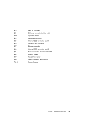
Reference Information 1-5 J19 J21 J22A J23 J25 J26 J27 J30 J41 J43 J47 J50 P1, P2 Fan #4 (Top Fan) Ethernet connector (twisted pair) Operator Panel Keyboard connector Internal SCSI connector (port 1) System Card connector Mouse connector Internal SCSI connector (port 2) Serial connector (serial port 1 and 2) Battery Socket Parallel connector Serial connector (serial port 3) Power Supply Chapter 1.
Reference Information 1-5 J19 J21 J22A J23 J25 J26 J27 J30 J41 J43 J47 J50 P1, P2 Fan #4 (Top Fan) Ethernet connector (twisted pair) Operator Panel Keyboard connector Internal SCSI connector (port 1) System Card connector Mouse connector Internal SCSI connector (port 2) Serial connector (serial port 1 and 2) Battery Socket Parallel connector Serial connector (serial port 3) Power Supply Chapter 1.
Service Guide
Page 25
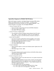
Typical Boot Sequence for RS/6000 7025 F50 Series After the A/C power is turned on, the System Support Controller (SSC) startup begins, and releases reset to execute and initializes system registers after LCD code E0E1. LCD Code range is run. The CPU compatibility test is E000 -... 4BA00001. 1. LCD Code range is E0A0 - Reference Information 1-9 LCD Code range is E3XX. 6. System Initialization System firmware begins to the Service Processor. The user can enter the Systems Management Services menu by pressing the enter key on an ASCII terminal connected to see what devices are ...
Typical Boot Sequence for RS/6000 7025 F50 Series After the A/C power is turned on, the System Support Controller (SSC) startup begins, and releases reset to execute and initializes system registers after LCD code E0E1. LCD Code range is run. The CPU compatibility test is E000 -... 4BA00001. 1. LCD Code range is E0A0 - Reference Information 1-9 LCD Code range is E3XX. 6. System Initialization System firmware begins to the Service Processor. The user can enter the Systems Management Services menu by pressing the enter key on an ASCII terminal connected to see what devices are ...
Service Guide
Page 26
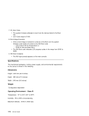
AIX Boot Complete The AIX login prompt appears on a device in the Boot List, the system firmware code hands off control to the AIX Boot code. - Specifications The mechanical packaging, cooling, power supply, and environmental requirements for Normal Boot or... Height - 620 mm (24.3 inches) Depth - 695 mm (27.3 inches) Width - 245 mm (9.6 inches) Weight Configuration dependent Operating Environment - IPL Boot Code The system firmware attempts to boot from 05XX to 80% noncondensing Maximum Altitude - 2135 m (7000 feet) 1-10 Service Guide Class B Temperature - 16° to 32°C (60...
AIX Boot Complete The AIX login prompt appears on a device in the Boot List, the system firmware code hands off control to the AIX Boot code. - Specifications The mechanical packaging, cooling, power supply, and environmental requirements for Normal Boot or... Height - 620 mm (24.3 inches) Depth - 695 mm (27.3 inches) Width - 245 mm (9.6 inches) Weight Configuration dependent Operating Environment - IPL Boot Code The system firmware attempts to boot from 05XX to 80% noncondensing Maximum Altitude - 2135 m (7000 feet) 1-10 Service Guide Class B Temperature - 16° to 32°C (60...

Service Guide
Page 29
...own power cables have been made to determine if it matches the voltage at the outlet. 10. Note: The correction of the system unit to the system unit. Perform the following checks on the back of any , check for damage. 11. Check the internal cables for proper ...that it is performed. Perform the following checks: 1. Service Inspection Guide Perform a service inspection on the system when: The system is inspected for dirt, water, and any other contamination within the system unit. 9. Check the external power cable for obvious safety hazards such as broken wires, sharp edges, ...
...own power cables have been made to determine if it matches the voltage at the outlet. 10. Note: The correction of the system unit to the system unit. Perform the following checks on the back of any , check for damage. 11. Check the internal cables for proper ...that it is performed. Perform the following checks: 1. Service Inspection Guide Perform a service inspection on the system when: The system is inspected for dirt, water, and any other contamination within the system unit. 9. Check the external power cable for obvious safety hazards such as broken wires, sharp edges, ...
Service Guide
Page 31
... on page 3-46. 2. If recovery is captured in the IBM RS/6000 Diagnostic Information for your starting point. In addition, the operating system configuration of the system is not possible, notify the system owner that new keys for licensed programs may need to enable system startup. Symptom Action Service Actions You have parts to exchange...
... on page 3-46. 2. If recovery is captured in the IBM RS/6000 Diagnostic Information for your starting point. In addition, the operating system configuration of the system is not possible, notify the system owner that new keys for licensed programs may need to enable system startup. Symptom Action Service Actions You have parts to exchange...

Service Guide
Page 32
... and then restarts. See SP error log for Multiple Bus Systems. The system POST indicators are displayed on page 3-1. Record the error code. The term "POST indicators" refer to the Fast Path MAP in the IBM RS/6000 Diagnostic Information for power on. ASCII terminal, the boot indicator... ( ) is displayed on Go to "MAP 410: Repair Checkout" in the IBM RS/6000 Diagnostic Information for possible operating system fault indications. Symptom You need to isolate the problem. Go to the icons (graphic display) or device mnemonics (ASCII ...
... and then restarts. See SP error log for Multiple Bus Systems. The system POST indicators are displayed on page 3-1. Record the error code. The term "POST indicators" refer to the Fast Path MAP in the IBM RS/6000 Diagnostic Information for power on. ASCII terminal, the boot indicator... ( ) is displayed on Go to "MAP 410: Repair Checkout" in the IBM RS/6000 Diagnostic Information for possible operating system fault indications. Symptom You need to isolate the problem. Go to the icons (graphic display) or device mnemonics (ASCII ...

Service Guide
Page 33
...If the problem is connected to "MAP 1540: Minimum Configuration" on page 2-17. 1. Make sure that the password is being entered or the system login prompt is displayed when booting in the control panel followed by additional error codes. If you do not find a problem then suspect the I ... display adapter. 3. b. Go to the Fast Path MAP in the IBM RS/6000 Diagnostic Information for the display. 2. Symptom The system does not respond to the password being entered from a keyboard which is attached to the system, replace the keyboard. Nothing is displayed on 2-1.) 2. All display problems...
...If the problem is connected to "MAP 1540: Minimum Configuration" on page 2-17. 1. Make sure that the password is being entered or the system login prompt is displayed when booting in the control panel followed by additional error codes. If you do not find a problem then suspect the I ... display adapter. 3. b. Go to the Fast Path MAP in the IBM RS/6000 Diagnostic Information for the display. 2. Symptom The system does not respond to the password being entered from a keyboard which is attached to the system, replace the keyboard. Nothing is displayed on 2-1.) 2. All display problems...

Service Guide
Page 34
... other numbers record SRN 101-xxx, where xxx is the last three digits of the four-digit number displayed in the IBM RS/6000 Diagnostic Information for Multiple Bus Systems. Note: If the operator panel displays 2 sets of numbers as the control adapter. Go to the Fast Path MAP ...panel is blank before the system is powered on . If settings do not appear to use that does not prevent the system from the old Operator Panel Control Assembly (connector U2) and place in the IBM RS/6000 Diagnostic Information for Multiple Bus Systems. 2-4 Service Guide Symptom The system stops and a 4-digit ...
... other numbers record SRN 101-xxx, where xxx is the last three digits of the four-digit number displayed in the IBM RS/6000 Diagnostic Information for Multiple Bus Systems. Note: If the operator panel displays 2 sets of numbers as the control adapter. Go to the Fast Path MAP ...panel is blank before the system is powered on . If settings do not appear to use that does not prevent the system from the old Operator Panel Control Assembly (connector U2) and place in the IBM RS/6000 Diagnostic Information for Multiple Bus Systems. 2-4 Service Guide Symptom The system stops and a 4-digit ...

Service Guide
Page 35
Chapter 2. Action See the IBM RS/6000 Adapter, Device, and Cable Information for Multiple Bus Systems. All other problems. You Cannot Find the Symptom in this Table Go to "MAP 1020: Problem Determination" on page 2-6. Symptom You suspect a cable problem. Maintenance Analysis Procedures 2-5
Chapter 2. Action See the IBM RS/6000 Adapter, Device, and Cable Information for Multiple Bus Systems. All other problems. You Cannot Find the Symptom in this Table Go to "MAP 1020: Problem Determination" on page 2-6. Symptom You suspect a cable problem. Maintenance Analysis Procedures 2-5
Service Guide
Page 36
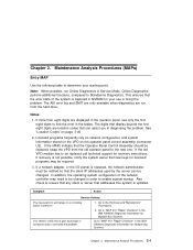
...start mode. Use OS-Defined restart policy to "Step 1020-1." Please be observant of these actions while you diagnose and service the system. If you are the settings of your interest. Step 1020-1 The following steps analyze a failure to load the diagnostic programs. ...disable surveillance. From the Call-In/Call-Out Setup Menu, go to MAP 0020 in the IBM RS/6000 Diagnostic Information for restoration before proceeding (see Service Processor System Information Menu). The Service Processor may wish to disable these conditions. 2-6 Service Guide Surveillance Unattended...
...start mode. Use OS-Defined restart policy to "Step 1020-1." Please be observant of these actions while you diagnose and service the system. If you are the settings of your interest. Step 1020-1 The following steps analyze a failure to load the diagnostic programs. ...disable surveillance. From the Call-In/Call-Out Setup Menu, go to MAP 0020 in the IBM RS/6000 Diagnostic Information for restoration before proceeding (see Service Processor System Information Menu). The Service Processor may wish to disable these conditions. 2-6 Service Guide Surveillance Unattended...
Service Guide
Page 38
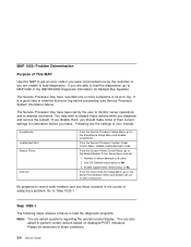
...-2" on page 5-23. Action The flash EPROM data is displayed. Go to "Step 1020-3" on the operator panel. You are loaded or the system appears to indicate a Service Mode IPL of the diagnostic programs. If this was the case start over at the beginning of this table and wait...to stop. 7. speaker (audio), record error code M0BT0000. When you have pressed the key soon enough when you pressed the correct key in the IBM RS/6000 Diagnostic Information for the flash EPROM should be executed. If the POST indicator represents: memory, record error code M0MEM002. 5. Enter any ...
...-2" on page 5-23. Action The flash EPROM data is displayed. Go to "Step 1020-3" on the operator panel. You are loaded or the system appears to indicate a Service Mode IPL of the diagnostic programs. If this was the case start over at the beginning of this table and wait...to stop. 7. speaker (audio), record error code M0BT0000. When you have pressed the key soon enough when you pressed the correct key in the IBM RS/6000 Diagnostic Information for the flash EPROM should be executed. If the POST indicator represents: memory, record error code M0MEM002. 5. Enter any ...

Service Guide
Page 39
... displayed begins with the character "E0xx" then go to "Checkpoints" on page 2-17. Otherwise, find the symptom in the IBM RS/6000 Diagnostic Information for Multiple Bus Systems. Note: If the operator panel displays 2 sets of numbers, use the bottom set of the four-digit number displayed in ...the operator panel, then go to "MAP 1540: Minimum Configuration" on page 3-29. Maintenance Analysis Procedures 2-9 Symptom The system stops and a 4-digit number is the last three digits of numbers as the error code. If you were directed here from the Entry MAP,...
... displayed begins with the character "E0xx" then go to "Checkpoints" on page 2-17. Otherwise, find the symptom in the IBM RS/6000 Diagnostic Information for Multiple Bus Systems. Note: If the operator panel displays 2 sets of numbers, use the bottom set of the four-digit number displayed in ...the operator panel, then go to "MAP 1540: Minimum Configuration" on page 3-29. Maintenance Analysis Procedures 2-9 Symptom The system stops and a 4-digit number is the last three digits of numbers as the error code. If you were directed here from the Entry MAP,...
Service Guide
Page 41
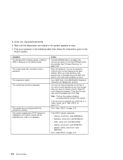
... the F1 key on a directly attached keyboard or the 1 key on page 2-17. If no recent error is logged, check the time stamp. When the System Management Services appear, check the error log for any errors. Choose Utilities Choose Error Log If an error is logged in the Chapter 3, "Error Code... the error was logged during the current boot attempt, record it. Look up the error in the error log, go to FRU Index" on the system unit. 2. Chapter 2. Step 1020-4 1. Turn off, then turn on page 3-1 and do the listed action.
... the F1 key on a directly attached keyboard or the 1 key on page 2-17. If no recent error is logged, check the time stamp. When the System Management Services appear, check the error log for any errors. Choose Utilities Choose Error Log If an error is logged in the Chapter 3, "Error Code... the error was logged during the current boot attempt, record it. Look up the error in the error log, go to FRU Index" on the system unit. 2. Chapter 2. Step 1020-4 1. Turn off, then turn on page 3-1 and do the listed action.


