Safety and Regulatory Information Desktops, Thin Clients, and Personal Workstations
Page 28
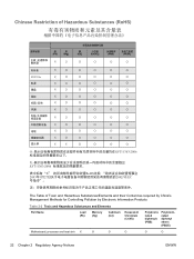
... 2-2 Toxic and Hazardous Substances and Elements Part Name Lead (Pb) Mercury (Hg) Cadmium (Cd) Hexavalent Chromium (Cr(VI)) Polybrominated biphenyls (PBB) Polybrominated diphenyl ethers (PBDE) Motherboard, processor and heat sink X O O O O O 22 Chapter 2 Regulatory Agency Notices ENWW
... 2-2 Toxic and Hazardous Substances and Elements Part Name Lead (Pb) Mercury (Hg) Cadmium (Cd) Hexavalent Chromium (Cr(VI)) Polybrominated biphenyls (PBB) Polybrominated diphenyl ethers (PBDE) Motherboard, processor and heat sink X O O O O O 22 Chapter 2 Regulatory Agency Notices ENWW
Start Here Guide
Page 10
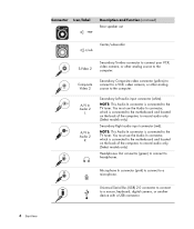
... Start Here Universal Serial Bus (USB) 2.0 connector to connect to a microphone. You must use the Audio In connector, which is connected to the motherboard and located on the back of the computer, to the computer. Composite Video 2 Secondary Composite video connector (yellow) to connect to a VCR, video ...(white). NOTE: This Audio In connector is connected to headphones. You must use the Audio In connector, which is connected to the motherboard and located on the back of the computer, to record audio only. (Select models only.) Headphones Out connector (green) to connect ...
... Start Here Universal Serial Bus (USB) 2.0 connector to connect to a microphone. You must use the Audio In connector, which is connected to the motherboard and located on the back of the computer, to the computer. Composite Video 2 Secondary Composite video connector (yellow) to connect to a VCR, video ...(white). NOTE: This Audio In connector is connected to headphones. You must use the Audio In connector, which is connected to the motherboard and located on the back of the computer, to record audio only. (Select models only.) Headphones Out connector (green) to connect ...
Start Here Guide
Page 12
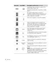
... Composite Video A/V In Audio 1 L S-video In connector to connect side speakers Side in a multichannel audio configuration. Composite Video In connector (yellow) to connect to the motherboard. Microphone In (Mic) (pink) to connect to connect front speakers. Line C/Sub (gold) connector to connect a TV or monitor. (Select models only.) See the documentation...
... Composite Video A/V In Audio 1 L S-video In connector to connect side speakers Side in a multichannel audio configuration. Composite Video In connector (yellow) to connect to the motherboard. Microphone In (Mic) (pink) to connect to connect front speakers. Line C/Sub (gold) connector to connect a TV or monitor. (Select models only.) See the documentation...

Start Here Guide
Page 13
... In connector which is connected to a digital audio device with digital output (select models only). Digital Audio Out Digital audio input (white) connects to the motherboard. Digital Out (orange) connects to a digital audio device with no set -top box connector (red). Connector Icon/label A/V In Audio 1 R TV/Cable Ant FM Ant...
... In connector which is connected to a digital audio device with digital output (select models only). Digital Audio Out Digital audio input (white) connects to the motherboard. Digital Out (orange) connects to a digital audio device with no set -top box connector (red). Connector Icon/label A/V In Audio 1 R TV/Cable Ant FM Ant...
Upgrading and Servicing Guide
Page 18
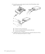
C - Connect to a primary hard disk drive. See "Opening and Closing the PC" on page 1. 14 Upgrading and Servicing Guide Connect to a secondary hard disk drive (select models only). B - Connect to the PC motherboard. 5 Complete the procedures to the back of the HP Pocket Media, diskette (floppy), or hard disk drive. 4 Connect the power and data cables to replace the front panel, replace the side panel, and close the PC. A B MASTER C SLAVE To CPU A -
C - Connect to a primary hard disk drive. See "Opening and Closing the PC" on page 1. 14 Upgrading and Servicing Guide Connect to a secondary hard disk drive (select models only). B - Connect to the PC motherboard. 5 Complete the procedures to the back of the HP Pocket Media, diskette (floppy), or hard disk drive. 4 Connect the power and data cables to replace the front panel, replace the side panel, and close the PC. A B MASTER C SLAVE To CPU A -
Upgrading and Servicing Guide
Page 25
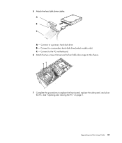
Connect to a secondary hard disk drive (select models only). B - See "Opening and Closing the PC" on page 1. 5 Attach the hard disk drive cables. A B MASTER C SLAVE To CPU A - Connect to a primary hard disk drive. Connect to the PC motherboard. 6 Attach the two screws that secure the hard disk drive cage to the chassis. 7 Complete the procedures to replace the front panel, replace the side panel, and close the PC. Upgrading and Servicing Guide 21 C -
Connect to a secondary hard disk drive (select models only). B - See "Opening and Closing the PC" on page 1. 5 Attach the hard disk drive cables. A B MASTER C SLAVE To CPU A - Connect to a primary hard disk drive. Connect to the PC motherboard. 6 Attach the two screws that secure the hard disk drive cage to the chassis. 7 Complete the procedures to replace the front panel, replace the side panel, and close the PC. Upgrading and Servicing Guide 21 C -
Upgrading and Servicing Guide
Page 26
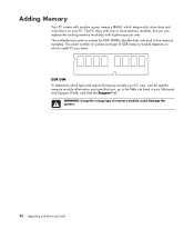
... or more memory modules, but you can replace the existing memory module(s) with random access memory (RAM), which model PC you have. WARNING: Using the wrong type of memory module your PC. The motherboard contains sockets for specific memory module information and specifications, go to the Web site listed in -line memory modules...
... or more memory modules, but you can replace the existing memory module(s) with random access memory (RAM), which model PC you have. WARNING: Using the wrong type of memory module your PC. The motherboard contains sockets for specific memory module information and specifications, go to the Web site listed in -line memory modules...
Upgrading and Servicing Guide
Page 27
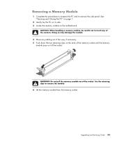
... page 1. 2 Gently lay the PC on its side. 3 Locate the memory sockets on the ends of the memory socket until the memory module pops out of the way, if necessary. 5 Push down the two retaining clips on the motherboard. Upgrading and Servicing Guide 23 Removing a Memory Module 1 Complete the... procedures to prepare the PC and to remove the module. 6 Lift the memory module from the memory socket.
... page 1. 2 Gently lay the PC on its side. 3 Locate the memory sockets on the ends of the memory socket until the memory module pops out of the way, if necessary. 5 Push down the two retaining clips on the motherboard. Upgrading and Servicing Guide 23 Removing a Memory Module 1 Complete the... procedures to prepare the PC and to remove the module. 6 Lift the memory module from the memory socket.
Upgrading and Servicing Guide
Page 30
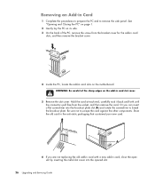
... card slot cover. 5 Remove the slot cover. Store the old card in Card 1 Complete the procedures to prepare the PC and to remove the side panel. A 6 If you can insert a flat screwdriver into the opened slot. 26 Upgrading... the bracket cover for the add-in card slots, and then remove the bracket cover. 4 Inside the PC, locate the add-in card slots on the add-in card, close the open slot by inserting the ...static packaging that contained your new card. See "Opening and Closing the PC" on page 1. 2 Gently lay the PC on its side. 3 On the back of the sharp edges on the motherboard.
... card slot cover. 5 Remove the slot cover. Store the old card in Card 1 Complete the procedures to prepare the PC and to remove the side panel. A 6 If you can insert a flat screwdriver into the opened slot. 26 Upgrading... the bracket cover for the add-in card slots, and then remove the bracket cover. 4 Inside the PC, locate the add-in card slots on the add-in card, close the open slot by inserting the ...static packaging that contained your new card. See "Opening and Closing the PC" on page 1. 2 Gently lay the PC on its side. 3 On the back of the sharp edges on the motherboard.
Upgrading and Servicing Guide
Page 32
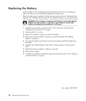
... cabling, if necessary, to reach the battery. 4 Remove any memory modules, if necessary, to close the PC. WARNING: There is incorrectly replaced. See "Opening and Closing the PC" on the motherboard provides backup power for the PC's timekeeping ability. Replace only with the same, or equivalent, type of explosion if the battery is danger...
... cabling, if necessary, to reach the battery. 4 Remove any memory modules, if necessary, to close the PC. WARNING: There is incorrectly replaced. See "Opening and Closing the PC" on the motherboard provides backup power for the PC's timekeeping ability. Replace only with the same, or equivalent, type of explosion if the battery is danger...


