Start Here Guide
Page 10
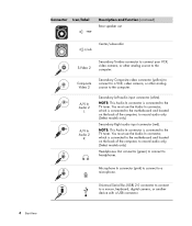
... source to the TV tuner. NOTE: This Audio In connector is connected to the motherboard and located on the back of the computer, to record audio only. (Select models only.) Headphones Out connector (green) to connect to record audio only. (Select models only.) Secondary Right audio input...(continued) Rear speaker out Center/subwoofer Secondary S-video connector to connect your VCR, S-video S-Video 2 video camera, or other analog source to the TV tuner. NOTE: This Audio In connector is connected to the motherboard and located on the back of the computer, to headphones. You...
... source to the TV tuner. NOTE: This Audio In connector is connected to the motherboard and located on the back of the computer, to record audio only. (Select models only.) Headphones Out connector (green) to connect to record audio only. (Select models only.) Secondary Right audio input...(continued) Rear speaker out Center/subwoofer Secondary S-video connector to connect your VCR, S-video S-Video 2 video camera, or other analog source to the TV tuner. NOTE: This Audio In connector is connected to the motherboard and located on the back of the computer, to headphones. You...
Start Here Guide
Page 12
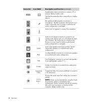
...using this primary left audio input from a set-top box output connector. Center Rear Audio Line In (blue) connector to connect to the motherboard. Some computers include this Audio In connector, which is activated. Line C/Sub (gold) connector to a microphone. Composite Video In... connector (yellow) to connect to connect a TV or monitor. (Select models only.) See the documentation that came with your display device. Connector...
...using this primary left audio input from a set-top box output connector. Center Rear Audio Line In (blue) connector to connect to the motherboard. Some computers include this Audio In connector, which is activated. Line C/Sub (gold) connector to a microphone. Composite Video In... connector (yellow) to connect to connect a TV or monitor. (Select models only.) See the documentation that came with your display device. Connector...

Start Here Guide
Page 13
...ends of the computer on the back of the cable to a VGA monitor. Setting Up Your Computer 7 Digital Audio Out Digital audio input (white) connects to your FM radio signal reception. Modem (Line In RJ-11) (select models only). Plug the other end to a digital audio device with ...models only.) TV In (TV antenna or cable input from set -top box.) FM In (radio antenna input) connects to the motherboard. Some computers include this Audio In connector which is connected to the FM antenna cable. Plug the FM radio antenna cable into the computer modem connector on the front of...
...ends of the computer on the back of the cable to a VGA monitor. Setting Up Your Computer 7 Digital Audio Out Digital audio input (white) connects to your FM radio signal reception. Modem (Line In RJ-11) (select models only). Plug the other end to a digital audio device with ...models only.) TV In (TV antenna or cable input from set -top box.) FM In (radio antenna input) connects to the motherboard. Some computers include this Audio In connector which is connected to the FM antenna cable. Plug the FM radio antenna cable into the computer modem connector on the front of...
Upgrading and Servicing Guide
Page 18
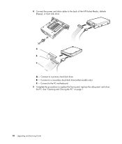
4 Connect the power and data cables to a primary hard disk drive. B - See "Opening and Closing the PC" on page 1. 14 Upgrading and Servicing Guide Connect to the back of the HP Pocket Media, diskette (floppy), or hard disk drive. Connect to replace the front panel, replace the side panel, and close the PC. Connect to the PC motherboard. 5 Complete the procedures to a secondary hard disk drive (select models only). C - A B MASTER C SLAVE To CPU A -
4 Connect the power and data cables to a primary hard disk drive. B - See "Opening and Closing the PC" on page 1. 14 Upgrading and Servicing Guide Connect to the back of the HP Pocket Media, diskette (floppy), or hard disk drive. Connect to replace the front panel, replace the side panel, and close the PC. Connect to the PC motherboard. 5 Complete the procedures to a secondary hard disk drive (select models only). C - A B MASTER C SLAVE To CPU A -
Upgrading and Servicing Guide
Page 25
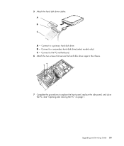
Connect to replace the front panel, replace the side panel, and close the PC. Connect to the PC motherboard. 6 Attach the two screws that secure the hard disk drive cage to the chassis. 7 Complete the procedures to a secondary hard disk drive (select models only). B - 5 Attach the hard disk drive cables. Connect to a primary hard disk drive. See "Opening and Closing the PC" on page 1. C - Upgrading and Servicing Guide 21 A B MASTER C SLAVE To CPU A -
Connect to replace the front panel, replace the side panel, and close the PC. Connect to the PC motherboard. 6 Attach the two screws that secure the hard disk drive cage to the chassis. 7 Complete the procedures to a secondary hard disk drive (select models only). B - 5 Attach the hard disk drive cables. Connect to a primary hard disk drive. See "Opening and Closing the PC" on page 1. C - Upgrading and Servicing Guide 21 A B MASTER C SLAVE To CPU A -


