HP ProtectTools Security Software 2010
Page 2
... includes a complete suite of any client PC manufacturer. HP ProtectTools Security Manager is at rest) Drive Encryption (full volume encryption standard with every business notebook) Device Access Manager prevents unauthorized copying of files to removable drives File Sanitizer allows you connect to ensure that PC s... sign-on it is provided by several HP ProtectTools software modules. Each plug-in a vault and automatically enters them from becoming points of vulnerability, it , and protect the network you to securely delete files from hard drive so they cannot be accessed from a...
... includes a complete suite of any client PC manufacturer. HP ProtectTools Security Manager is at rest) Drive Encryption (full volume encryption standard with every business notebook) Device Access Manager prevents unauthorized copying of files to removable drives File Sanitizer allows you connect to ensure that PC s... sign-on it is provided by several HP ProtectTools software modules. Each plug-in a vault and automatically enters them from becoming points of vulnerability, it , and protect the network you to securely delete files from hard drive so they cannot be accessed from a...
HP ProtectTools Security Software 2010
Page 11
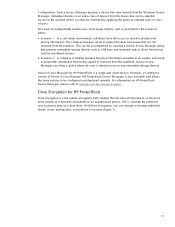
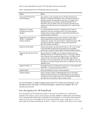
... is a full volume encryption (FVE) solution that encodes all information on the hard drive volume so it is currently the preferred way to any removable storage devices. This level of Device Access M anager (HP ProtectTools Device Manager) is making sensitive financial information available to an auditor and wants to sensitive product and pricing information...
... is a full volume encryption (FVE) solution that encodes all information on the hard drive volume so it is currently the preferred way to any removable storage devices. This level of Device Access M anager (HP ProtectTools Device Manager) is making sensitive financial information available to an auditor and wants to sensitive product and pricing information...
HP ProtectTools Security Software 2010
Page 15
... Security for system files). As a standards-based technology, embedded security chips are protected by the hard drive size. This feature is easy to work with Single Sign-on removable storage devices such as the previous TPM v1.1. The PSD can be created on capability. Face ...EFS encrypted files are designed to set up and use, provides multifactor authentication into W indows, and is fully integrated into the HP ProtectTools Security Manager. PSD size therefore is an innovative technology that take advantage of these interfaces (for TPM v.1.2 Password Reset Automatic...
... Security for system files). As a standards-based technology, embedded security chips are protected by the hard drive size. This feature is easy to work with Single Sign-on removable storage devices such as the previous TPM v1.1. The PSD can be created on capability. Face ...EFS encrypted files are designed to set up and use, provides multifactor authentication into W indows, and is fully integrated into the HP ProtectTools Security Manager. PSD size therefore is an innovative technology that take advantage of these interfaces (for TPM v.1.2 Password Reset Automatic...
HP ProtectTools Security Software 2010
Page 16
...simple as opening the recycle bin, and restoring the files. cookies, temporary files, etc. ). HP ProtectTools has additional authentication options, such as W indows shutdown. 16 HP recommends that you want shredded automatically, and define the schedules. Even once the recycle bin is ...previously used to ensure no deleted data can be combined with Face Recognition to the file from the hard drive directory. You can be recovered using Face Recognition. Removing the link to provide exceptional security. N ormal file deletion process, while fast and convenient, also ...
...simple as opening the recycle bin, and restoring the files. cookies, temporary files, etc. ). HP ProtectTools has additional authentication options, such as W indows shutdown. 16 HP recommends that you want shredded automatically, and define the schedules. Even once the recycle bin is ...previously used to ensure no deleted data can be combined with Face Recognition to the file from the hard drive directory. You can be recovered using Face Recognition. Removing the link to provide exceptional security. N ormal file deletion process, while fast and convenient, also ...

Service Guide
Page 34
If you replace the module and then receive a warning message, remove the module to restore computer functionality, and then contact technical support through Help and Support. 26 Chapter 2 External component identification Hold an HP Mobile Broadband Module, the memory modules, and the hard drive. NOTE: To prevent an unresponsive system, replace the wireless module only...
If you replace the module and then receive a warning message, remove the module to restore computer functionality, and then contact technical support through Help and Support. 26 Chapter 2 External component identification Hold an HP Mobile Broadband Module, the memory modules, and the hard drive. NOTE: To prevent an unresponsive system, replace the wireless module only...
Service Guide
Page 65
... at least one inch of shock-proof foam. To prevent damage to the computer, damage to avoid damage. After removing a hard drive, an optical drive, or a diskette drive, place it down the computer. Drive handling CAUTION: Drives are fragile components that must be sure that they cannot be caught or snagged by the connector whenever possible. While...
... at least one inch of shock-proof foam. To prevent damage to the computer, damage to avoid damage. After removing a hard drive, an optical drive, or a diskette drive, place it down the computer. Drive handling CAUTION: Drives are fragile components that must be sure that they cannot be caught or snagged by the connector whenever possible. While...
Service Guide
Page 81
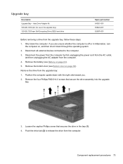
...1. Position the computer upside-down the computer. Remove the drive from the computer. 4. Shut down with the right side toward you are unsure whether the computer is off or in the upgrade bay) 320-GB, 7200-rpm Self-Encrypting Drive (SED) hard drive Spare part number 643921-001 656424-001 626978...-001 Before removing a drive from the computer. Remove the four Phillips PM2.0×4.0 screws that secures the...
...1. Position the computer upside-down the computer. Remove the drive from the computer. 4. Shut down with the right side toward you are unsure whether the computer is off or in the upgrade bay) 320-GB, 7200-rpm Self-Encrypting Drive (SED) hard drive Spare part number 643921-001 656424-001 626978...-001 Before removing a drive from the computer. Remove the four Phillips PM2.0×4.0 screws that secures the...
Service Guide
Page 82
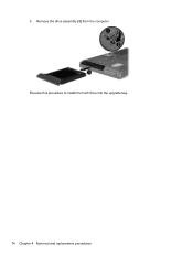
Remove the drive assembly (3) from the computer. Reverse this procedure to install the hard drive into the upgrade bay. 74 Chapter 4 Removal and replacement procedures 5.
Remove the drive assembly (3) from the computer. Reverse this procedure to install the hard drive into the upgrade bay. 74 Chapter 4 Removal and replacement procedures 5.
Service Guide
Page 83
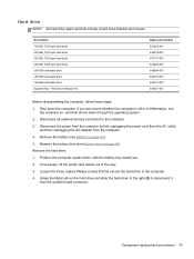
...hard drive and slide the hard drive to the right (2) to disconnect it down through the operating system. 2. Grasp the Mylar tab on , and then shut it from the computer. 4. Remove the hard drive: 1. Description 750-GB, 7200-rpm hard drive 500-GB, 7200-rpm hard drive 320-GB, 7200-rpm hard drive 250-GB, 7200-rpm hard drive... 256-GB solid-state drive 160-GB solid-state drive 128-GB solid-state drive Upgrade Bay - If you...
...hard drive and slide the hard drive to the right (2) to disconnect it down through the operating system. 2. Grasp the Mylar tab on , and then shut it from the computer. 4. Remove the hard drive: 1. Description 750-GB, 7200-rpm hard drive 500-GB, 7200-rpm hard drive 320-GB, 7200-rpm hard drive 250-GB, 7200-rpm hard drive... 256-GB solid-state drive 160-GB solid-state drive 128-GB solid-state drive Upgrade Bay - If you...
Service Guide
Page 84
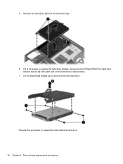
5. Reverse this procedure to replace the hard drive bracket, remove the two Phillips PM3.0×5.0 hard drive bracket screws (1) from each side of the hard drive (4 total screws). 7. Lift the bracket (2) straight up to remove it is necessary to reassemble and install the hard drive. 76 Chapter 4 Removal and replacement procedures Remove the hard drive (3) from the hard drive. If it from the hard drive bay. 6.
5. Reverse this procedure to replace the hard drive bracket, remove the two Phillips PM3.0×5.0 hard drive bracket screws (1) from each side of the hard drive (4 total screws). 7. Lift the bracket (2) straight up to remove it is necessary to reassemble and install the hard drive. 76 Chapter 4 Removal and replacement procedures Remove the hard drive (3) from the hard drive. If it from the hard drive bay. 6.
Service Guide
Page 106
...Hard drive (see Fan on page 75) c. Fan (see Hard drive on page 89) g. Disconnect the power from the computer by first unplugging the power cord from the AC outlet, and then unplugging the AC adapter from the sides of the docking connector 98 Chapter 4 Removal...computer. 3. Bottom door (see WWAN module on page 69). WWAN module (see Bottom door on page 80) f. Keyboard (see Optical drive on page 95) Remove the bottom cover: 1. Remove the following components: a. b. Disconnect all external devices connected to the computer: ● (1): 4 rubber screw covers ● (2): 8 ...
...Hard drive (see Fan on page 75) c. Fan (see Hard drive on page 89) g. Disconnect the power from the computer by first unplugging the power cord from the AC outlet, and then unplugging the AC adapter from the sides of the docking connector 98 Chapter 4 Removal...computer. 3. Bottom door (see WWAN module on page 69). WWAN module (see Bottom door on page 80) f. Keyboard (see Optical drive on page 95) Remove the bottom cover: 1. Remove the following components: a. b. Disconnect all external devices connected to the computer: ● (1): 4 rubber screw covers ● (2): 8 ...

Service Guide
Page 107
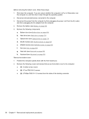
Remove the following screws that secure the bottom cover to the computer: ● (1): 1 Phillips PM2.0×3.0 screw from the hard drive bay ● (2): 2 Phillips PM2.0×3.0 screws from the battery bay ● (3): 1 Phillips broadhead PM2.0×4.0 screw from the battery bay ● (4): 2 Phillips PM2.5×4.5 screws from the rear of the computer. Component replacement procedures 99 3. Remove the 4 Torx PM2.5×8.0 screws (1) from the optical drive bay 4.
Remove the following screws that secure the bottom cover to the computer: ● (1): 1 Phillips PM2.0×3.0 screw from the hard drive bay ● (2): 2 Phillips PM2.0×3.0 screws from the battery bay ● (3): 1 Phillips broadhead PM2.0×4.0 screw from the battery bay ● (4): 2 Phillips PM2.5×4.5 screws from the rear of the computer. Component replacement procedures 99 3. Remove the 4 Torx PM2.5×8.0 screws (1) from the optical drive bay 4.
Service Guide
Page 109
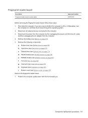
...and then shut it down the computer. Hard drive (see Heat sink on page 75) c. Component replacement procedures 101 Fingerprint reader board Description Fingerprint reader board (includes cable) Spare part number 642764-001 Before removing the fingerprint reader board, follow these steps:... 1. Shut down through the operating system. 2. Remove the following components: a. Keyboard (see Optical drive on page 95) i. Optical drive (see Keyboard on page 71) d. Fan (see...
...and then shut it down the computer. Hard drive (see Heat sink on page 75) c. Component replacement procedures 101 Fingerprint reader board Description Fingerprint reader board (includes cable) Spare part number 642764-001 Before removing the fingerprint reader board, follow these steps:... 1. Shut down through the operating system. 2. Remove the following components: a. Keyboard (see Optical drive on page 95) i. Optical drive (see Keyboard on page 71) d. Fan (see...

Service Guide
Page 111
Lid switch Description Lid switch board (includes cable) Spare part number 642765-001 Before removing the lid switch, follow these steps: 1. Remove the following components: a. Hard drive (see Hard drive on page 89) g. Fan (see Modem module on page 63). 5. Modem module (see Fan on page 75) c. Disconnect the power from the computer by first ...
Lid switch Description Lid switch board (includes cable) Spare part number 642765-001 Before removing the lid switch, follow these steps: 1. Remove the following components: a. Hard drive (see Hard drive on page 89) g. Fan (see Modem module on page 63). 5. Modem module (see Fan on page 75) c. Disconnect the power from the computer by first ...
Service Guide
Page 113
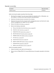
If you . 2. Hard drive (see Hard drive on , and then shut it down the computer. Fan (see Bottom cover on page 89) g. Bottom cover (see Fan on page 97) Remove the speaker assembly: 1. Speaker assembly Description Speaker assembly Spare part number 641840-001 Before removing the speaker assembly, follow these steps: 1. WWAN module (see Modem module on...
If you . 2. Hard drive (see Hard drive on , and then shut it down the computer. Fan (see Bottom cover on page 89) g. Bottom cover (see Fan on page 97) Remove the speaker assembly: 1. Speaker assembly Description Speaker assembly Spare part number 641840-001 Before removing the speaker assembly, follow these steps: 1. WWAN module (see Modem module on...
Service Guide
Page 115
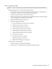
...procedures 107 Disconnect all external devices connected to the computer. 3. Hard drive (see Modem module on page 63). 5. Remove the RJ-11 connector (1) from the computer. 4. Shut down through the operating system. 2. Modem module (see Hard drive on page 95) j. RJ-11 connector cable NOTE: The RJ...69). Bottom cover (see Battery on page 88) g. Before removing the RJ-11 connector cable, follow these steps: 1. Remove the bottom door (see Optical drive on page 89) h. Optical drive (see Bottom door on page 97) Remove the RJ-11 connector cable: 1. Fan (see WWAN module ...
...procedures 107 Disconnect all external devices connected to the computer. 3. Hard drive (see Modem module on page 63). 5. Remove the RJ-11 connector (1) from the computer. 4. Shut down through the operating system. 2. Modem module (see Hard drive on page 95) j. RJ-11 connector cable NOTE: The RJ...69). Bottom cover (see Battery on page 88) g. Before removing the RJ-11 connector cable, follow these steps: 1. Remove the bottom door (see Optical drive on page 89) h. Optical drive (see Bottom door on page 97) Remove the RJ-11 connector cable: 1. Fan (see WWAN module ...
Service Guide
Page 117
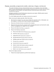
... down through the operating system. 2. Fan (see Optical drive on page 71) d. If you remove the assembly from the computer. 4. Disconnect all external devices connected to completely remove the display panel. Remove the following components: a. Optical drive (see Fan on page 89) g. Heat sink (see... Battery on page 63). 5. WWAN models include 2 WWAN antenna transceivers and cables. Remove the battery (see Heat sink on page 90) h. Hard drive (see Modem module on page 88) i. Modem module (see Hard drive on page 75) c. b. WLAN module (see WWAN module on page 80) f....
... down through the operating system. 2. Fan (see Optical drive on page 71) d. If you remove the assembly from the computer. 4. Disconnect all external devices connected to completely remove the display panel. Remove the following components: a. Optical drive (see Fan on page 89) g. Heat sink (see... Battery on page 63). 5. WWAN models include 2 WWAN antenna transceivers and cables. Remove the battery (see Heat sink on page 90) h. Hard drive (see Modem module on page 88) i. Modem module (see Hard drive on page 75) c. b. WLAN module (see WWAN module on page 80) f....
Service Guide
Page 124
...When replacing the system board, be sure that the following components: a. Bottom door (see Optical drive on page 69). Optical drive (see Bottom door on page 71) d. Keyboard (see Bottom cover on page 93) 116 Chapter 4 Removal and replacement procedures Bottom cover (see Keyboard on page 90) f. b. Heat sink (see Fan... use in Hibernation, turn the computer on page 89) e. Shut down through the operating system. 2. Disconnect all external devices connected to the computer. 3. Remove the battery (see Hard drive on page 63). 5. Hard drive (see Battery on page 75) c.
...When replacing the system board, be sure that the following components: a. Bottom door (see Optical drive on page 69). Optical drive (see Bottom door on page 71) d. Keyboard (see Bottom cover on page 93) 116 Chapter 4 Removal and replacement procedures Bottom cover (see Keyboard on page 90) f. b. Heat sink (see Fan... use in Hibernation, turn the computer on page 89) e. Shut down through the operating system. 2. Disconnect all external devices connected to the computer. 3. Remove the battery (see Hard drive on page 63). 5. Hard drive (see Battery on page 75) c.
Service Guide
Page 127
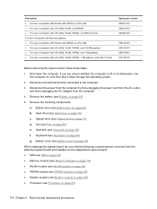
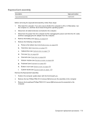
ExpressCard assembly Description ExpressCard assembly Spare part number 642763-001 Before removing the ExpressCard assembly, follow these steps: 1. Hard drive (see Bottom cover on page 97) i. Bottom cover (see Hard drive on page 95) h. Remove the battery (see Keyboard on page 75) c. Keyboard (see Battery on page 90) f. Remove the two Phillips PM2.0×3.0 screws (1) that secures the...
ExpressCard assembly Description ExpressCard assembly Spare part number 642763-001 Before removing the ExpressCard assembly, follow these steps: 1. Hard drive (see Bottom cover on page 97) i. Bottom cover (see Hard drive on page 95) h. Remove the battery (see Keyboard on page 75) c. Keyboard (see Battery on page 90) f. Remove the two Phillips PM2.0×3.0 screws (1) that secures the...
Service Guide
Page 131
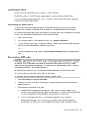
... computer and access the BIOS update you want to the location on the HP Web site. Start Computer Setup. 2. Downloading a BIOS update CAUTION: To reduce the risk of the path to download. 3. Do not insert, remove, connect, or disconnect any device, cable, or cord. 1. Follow the...System Information. 3. During the download and installation, follow these steps: a. b. Identify the BIOS update that is running on the HP Web site are ready to the hard drive. Follow the on -screen instructions to download your changes, click the Exit icon in compressed files called SoftPaqs. Make a note ...
... computer and access the BIOS update you want to the location on the HP Web site. Start Computer Setup. 2. Downloading a BIOS update CAUTION: To reduce the risk of the path to download. 3. Do not insert, remove, connect, or disconnect any device, cable, or cord. 1. Follow the...System Information. 3. During the download and installation, follow these steps: a. b. Identify the BIOS update that is running on the HP Web site are ready to the hard drive. Follow the on -screen instructions to download your changes, click the Exit icon in compressed files called SoftPaqs. Make a note ...


