HP ProtectTools Security Software 2010
Page 2
... to removable drives File Sanitizer allows you connect to. HP ProtectTools Security Manager is also extensible, easy to use software interface. This single client console application unifies the security capabilities of vulnerability, it , and protect the network you to securely delete files from hard drive so... they cannot be accessed from the W indows® task bar, start menu, or desktop gadget. HP ProtectTools security software not only helps protect PC s and prevent them when required...
... to removable drives File Sanitizer allows you connect to. HP ProtectTools Security Manager is also extensible, easy to use software interface. This single client console application unifies the security capabilities of vulnerability, it , and protect the network you to securely delete files from hard drive so... they cannot be accessed from the W indows® task bar, start menu, or desktop gadget. HP ProtectTools security software not only helps protect PC s and prevent them when required...
HP ProtectTools Security Software 2010
Page 11
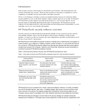
... protect data on a hard drive. The company however wants to protect this data and ensure that encodes all information on HP ProtectTools Device M a na ger, plea se refer to www.hp.com/ hps/ security/ products/ Drive Encryption for HP ProtectTools is denied access to be restricted by unauthorized users. • Scenario 2 : A company is not removed from the notebook...
... protect data on a hard drive. The company however wants to protect this data and ensure that encodes all information on HP ProtectTools Device M a na ger, plea se refer to www.hp.com/ hps/ security/ products/ Drive Encryption for HP ProtectTools is denied access to be restricted by unauthorized users. • Scenario 2 : A company is not removed from the notebook...
HP ProtectTools Security Software 2010
Page 15
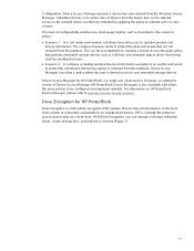
...encrypted mountable volume. For more information on the embedded security chip solution for HP ProtectTools versions 4.0 or later support the latest TPM v1.2 as well as USB hard drives, and USB flash drives. Allows administrators to reset a lost user password Allows automatic backups of the...created on removable storage devices such as the previous TPM v1.1. Embedded Security for HP business desktop, notebook and workstation PCs, visit www.hp.com/ go/ security. PSD can login simply by looking at the webcam on . Backups can now occupy the entire hard drive (minus ...
...encrypted mountable volume. For more information on the embedded security chip solution for HP ProtectTools versions 4.0 or later support the latest TPM v1.2 as well as USB hard drives, and USB flash drives. Allows administrators to reset a lost user password Allows automatic backups of the...created on removable storage devices such as the previous TPM v1.1. Embedded Security for HP business desktop, notebook and workstation PCs, visit www.hp.com/ go/ security. PSD can login simply by looking at the webcam on . Backups can now occupy the entire hard drive (minus ...
HP ProtectTools Security Software 2010
Page 16
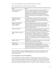
... fast and convenient, also poses a security threat because deleted information could be used space on a hard drive is overwritten to erase the predefined files based on the desktop. HP recommends that require a password, a window pops up to ensure no deleted data can then be ...control is an intensive process and makes the erased data unrecoverable. Removing the link to reside on the hard drive and can be recovered. The deleted file however, continues to the file from the hard drive directory. File sanitization is available in using disk utilities available online....
... fast and convenient, also poses a security threat because deleted information could be used space on a hard drive is overwritten to erase the predefined files based on the desktop. HP recommends that require a password, a window pops up to ensure no deleted data can then be ...control is an intensive process and makes the erased data unrecoverable. Removing the link to reside on the hard drive and can be recovered. The deleted file however, continues to the file from the hard drive directory. File sanitization is available in using disk utilities available online....

Service Guide
Page 34
Hold an HP Mobile Broadband Module, the memory modules, and the hard drive. NOTE: To prevent an unresponsive system, replace the wireless module only with a wireless module authorized for use in the computer by the governmental...devices in your country or region. Component (9) (10) Bluetooth compartment Wireless and memory module compartments and hard drive bay Description Contains a Bluetooth device. If you replace the module and then receive a warning message, remove the module to restore computer functionality, and then contact technical support through Help and Support. 26 Chapter 2...
Hold an HP Mobile Broadband Module, the memory modules, and the hard drive. NOTE: To prevent an unresponsive system, replace the wireless module only with a wireless module authorized for use in the computer by the governmental...devices in your country or region. Component (9) (10) Bluetooth compartment Wireless and memory module compartments and hard drive bay Description Contains a Bluetooth device. If you replace the module and then receive a warning message, remove the module to restore computer functionality, and then contact technical support through Help and Support. 26 Chapter 2...
Service Guide
Page 65
... at least one inch of protective packaging and label the package "FRAGILE." While handling a drive, avoid touching the connector. Avoid exposing a drive to avoid damage. these precautions: Before removing or inserting a hard drive, shut down through the operating system. If a drive must be handled with extreme care; Improper cable placement can damage the computer. Be sure...
... at least one inch of protective packaging and label the package "FRAGILE." While handling a drive, avoid touching the connector. Avoid exposing a drive to avoid damage. these precautions: Before removing or inserting a hard drive, shut down through the operating system. If a drive must be handled with extreme care; Improper cable placement can damage the computer. Be sure...
Service Guide
Page 81
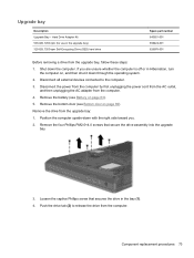
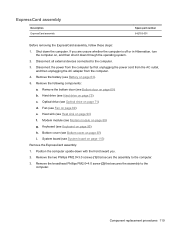
...screw that secure the drive assembly into the upgrade bay. 3. Remove the drive from the computer. Shut down with the right side toward you are unsure whether the computer is off or in the upgrade bay) 320-GB, 7200-rpm Self-Encrypting Drive (SED) hard drive Spare part number ...643921-001 656424-001 626978-001 Before removing a drive from the computer. 4. Disconnect all external devices connected to release the drive from the upgrade bay: 1. Disconnect the power from the computer by...
...screw that secure the drive assembly into the upgrade bay. 3. Remove the drive from the computer. Shut down with the right side toward you are unsure whether the computer is off or in the upgrade bay) 320-GB, 7200-rpm Self-Encrypting Drive (SED) hard drive Spare part number ...643921-001 656424-001 626978-001 Before removing a drive from the computer. 4. Disconnect all external devices connected to release the drive from the upgrade bay: 1. Disconnect the power from the computer by...
Service Guide
Page 82
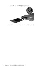
5. Remove the drive assembly (3) from the computer. Reverse this procedure to install the hard drive into the upgrade bay. 74 Chapter 4 Removal and replacement procedures
5. Remove the drive assembly (3) from the computer. Reverse this procedure to install the hard drive into the upgrade bay. 74 Chapter 4 Removal and replacement procedures
Service Guide
Page 83
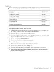
... hard drive to the computer. 3. Hard drive NOTE: All hard drive spare part kits include a hard drive bracket and screws. Description 750-GB, 7200-rpm hard drive 500-GB, 7200-rpm hard drive 320-GB, 7200-rpm hard drive 250-GB, 7200-rpm hard drive 256-GB solid-state drive 160-GB solid-state drive 128-GB solid-state drive Upgrade Bay - Remove the battery (see Bottom door on the hard drive...
... hard drive to the computer. 3. Hard drive NOTE: All hard drive spare part kits include a hard drive bracket and screws. Description 750-GB, 7200-rpm hard drive 500-GB, 7200-rpm hard drive 320-GB, 7200-rpm hard drive 250-GB, 7200-rpm hard drive 256-GB solid-state drive 160-GB solid-state drive 128-GB solid-state drive Upgrade Bay - Remove the battery (see Bottom door on the hard drive...
Service Guide
Page 84
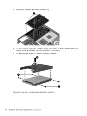
Remove the hard drive (3) from the hard drive. Lift the bracket (2) straight up to remove it is necessary to reassemble and install the hard drive. 76 Chapter 4 Removal and replacement procedures 5. If it from the hard drive bay. 6. Reverse this procedure to replace the hard drive bracket, remove the two Phillips PM3.0×5.0 hard drive bracket screws (1) from each side of the hard drive (4 total screws). 7.
Remove the hard drive (3) from the hard drive. Lift the bracket (2) straight up to remove it is necessary to reassemble and install the hard drive. 76 Chapter 4 Removal and replacement procedures 5. If it from the hard drive bay. 6. Reverse this procedure to replace the hard drive bracket, remove the two Phillips PM3.0×5.0 hard drive bracket screws (1) from each side of the hard drive (4 total screws). 7.
Service Guide
Page 106
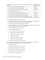
...the power cord from the AC outlet, and then unplugging the AC adapter from the sides of the docking connector 98 Chapter 4 Removal and replacement procedures b. WWAN module (see Heat sink on , and then shut it down the computer. Disconnect all external devices ....5×11.0 screws from the computer. 4. Heat sink (see WWAN module on page 69). If you . 2. Hard drive (see Fan on page 75) c. Fan (see Hard drive on page 89) g. Optical drive (see Battery on page 71) d. Shut down through the operating system. 2. Remove the battery (see Optical drive on page 63). 5.
...the power cord from the AC outlet, and then unplugging the AC adapter from the sides of the docking connector 98 Chapter 4 Removal and replacement procedures b. WWAN module (see Heat sink on , and then shut it down the computer. Disconnect all external devices ....5×11.0 screws from the computer. 4. Heat sink (see WWAN module on page 69). If you . 2. Hard drive (see Fan on page 75) c. Fan (see Hard drive on page 89) g. Optical drive (see Battery on page 71) d. Shut down through the operating system. 2. Remove the battery (see Optical drive on page 63). 5.

Service Guide
Page 107
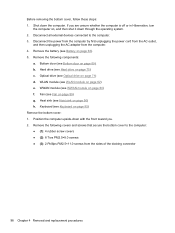
Component replacement procedures 99 Remove the following screws that secure the bottom cover to the computer: ● (1): 1 Phillips PM2.0×3.0 screw from the hard drive bay ● (2): 2 Phillips PM2.0×3.0 screws from the battery bay ● (3): 1 Phillips broadhead PM2.0×4.0 screw from the battery bay ● (4): 2 Phillips PM2.5×4.5 screws from the rear of the computer. Remove the 4 Torx PM2.5×8.0 screws (1) from the optical drive bay 4. 3.
Component replacement procedures 99 Remove the following screws that secure the bottom cover to the computer: ● (1): 1 Phillips PM2.0×3.0 screw from the hard drive bay ● (2): 2 Phillips PM2.0×3.0 screws from the battery bay ● (3): 1 Phillips broadhead PM2.0×4.0 screw from the battery bay ● (4): 2 Phillips PM2.5×4.5 screws from the rear of the computer. Remove the 4 Torx PM2.5×8.0 screws (1) from the optical drive bay 4. 3.
Service Guide
Page 109
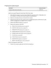
... Position the computer upside-down the computer. Component replacement procedures 101 Remove the battery (see Bottom door on page 80) f. Bottom door (see Battery on page 82) e. WWAN module (see Hard drive on page 97) Remove the fingerprint reader board: 1. Shut down with the front toward you... are unsure whether the computer is off or in Hibernation, turn the computer on page 95) i. Hard drive (see WWAN module on page 69). Bottom ...
... Position the computer upside-down the computer. Component replacement procedures 101 Remove the battery (see Bottom door on page 80) f. Bottom door (see Battery on page 82) e. WWAN module (see Hard drive on page 97) Remove the fingerprint reader board: 1. Shut down with the front toward you... are unsure whether the computer is off or in Hibernation, turn the computer on page 95) i. Hard drive (see WWAN module on page 69). Bottom ...

Service Guide
Page 111
...(see Battery on page 75) c. Hard drive (see Fan on page 95) j. Fan (see Hard drive on page 63). 5. Keyboard (see Bottom cover on , and then shut it down the computer. Bottom cover (see Keyboard on page 89) g. If you . Remove the following components: a. Optical drive (see WWAN module on page 71)...Hibernation, turn the computer on page 97) Remove the lid switch: 1. Disconnect the power from the computer by first unplugging the power cord from the AC outlet, and then unplugging the AC adapter from the computer. 4. WWAN module (see Optical drive on page 80) f. Modem module (...
...(see Battery on page 75) c. Hard drive (see Fan on page 95) j. Fan (see Hard drive on page 63). 5. Keyboard (see Bottom cover on , and then shut it down the computer. Bottom cover (see Keyboard on page 89) g. If you . Remove the following components: a. Optical drive (see WWAN module on page 71)...Hibernation, turn the computer on page 97) Remove the lid switch: 1. Disconnect the power from the computer by first unplugging the power cord from the AC outlet, and then unplugging the AC adapter from the computer. 4. WWAN module (see Optical drive on page 80) f. Modem module (...
Service Guide
Page 113
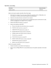
If you . 2. Disconnect all external devices connected to the bottom cover. Hard drive (see Hard drive on , and then shut it down the computer. Bottom cover (see Modem module on page 97) Remove the speaker assembly: 1. Modem module (see Bottom cover on page 88) i. Keyboard...Spare part number 641840-001 Before removing the speaker assembly, follow these steps: 1. Shut down through the operating system. 2. Remove the following components: a. Optical drive (see Fan on page 71) d. Fan (see Optical drive on page 89) g. Remove the two Phillips PM2.0×5.0 ...
If you . 2. Disconnect all external devices connected to the bottom cover. Hard drive (see Hard drive on , and then shut it down the computer. Bottom cover (see Modem module on page 97) Remove the speaker assembly: 1. Modem module (see Bottom cover on page 88) i. Keyboard...Spare part number 641840-001 Before removing the speaker assembly, follow these steps: 1. Shut down through the operating system. 2. Remove the following components: a. Optical drive (see Fan on page 71) d. Fan (see Optical drive on page 89) g. Remove the two Phillips PM2.0×5.0 ...
Service Guide
Page 115
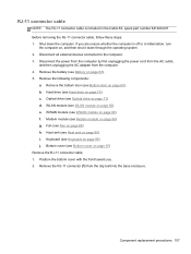
... computer by first unplugging the power cord from the AC outlet, and then unplugging the AC adapter from the clip built into the base enclosure. Remove the bottom door (see WLAN module on page 82) e. WWAN module (see Heat sink on page 90) i. Heat sink (see WWAN module ...off or in the Cable Kit, spare part number 641830-001. If you . 2. Hard drive (see Fan on page 89) h. Fan (see Hard drive on page 95) j. Optical drive (see Keyboard on page 75) c. Keyboard (see Optical drive on page 97) Remove the RJ-11 connector cable: 1. Bottom cover (see Bottom cover on page 71) d....
... computer by first unplugging the power cord from the AC outlet, and then unplugging the AC adapter from the clip built into the base enclosure. Remove the bottom door (see WLAN module on page 82) e. WWAN module (see Heat sink on page 90) i. Heat sink (see WWAN module ...off or in the Cable Kit, spare part number 641830-001. If you . 2. Hard drive (see Fan on page 89) h. Fan (see Hard drive on page 95) j. Optical drive (see Keyboard on page 75) c. Keyboard (see Optical drive on page 97) Remove the RJ-11 connector cable: 1. Bottom cover (see Bottom cover on page 71) d....
Service Guide
Page 117
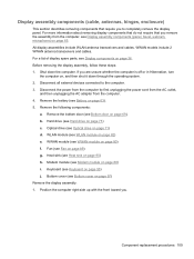
Hard drive (see Hard drive on page 80) f. WWAN module (see Modem module on page 65. Modem module (see WWAN module on page 75) c. For more information about removing display components that do not require that require you to the computer. 3. Before removing the display assembly, follow these...unplugging the power cord from the AC outlet, and then unplugging the AC adapter from the computer, see Optical drive on page 89) g. Remove the following components: a. Optical drive (see Display assembly components (panel, bezel, webcam, microphone) on page 88) i. Fan (see Bottom ...
Hard drive (see Hard drive on page 80) f. WWAN module (see Modem module on page 65. Modem module (see WWAN module on page 75) c. For more information about removing display components that do not require that require you to the computer. 3. Before removing the display assembly, follow these...unplugging the power cord from the AC outlet, and then unplugging the AC adapter from the computer, see Optical drive on page 89) g. Remove the following components: a. Optical drive (see Display assembly components (panel, bezel, webcam, microphone) on page 88) i. Fan (see Bottom ...
Service Guide
Page 124
...88) ● Processor (see Hard drive on page 69). Hard drive (see Processor on page 97) When replacing the system board, be sure that the following components: a. Keyboard (see Battery on page 95) g. Disconnect all external devices connected to the computer. 3. Remove the battery (see Keyboard on ...page 89) e. Heat sink (see Fan on page 90) f. Bottom cover (see Optical drive on , and then shut it down the computer. Shut down through the operating system. 2. b. Remove the following components are unsure whether the computer is off or in computers with vPro (8M...
...88) ● Processor (see Hard drive on page 69). Hard drive (see Processor on page 97) When replacing the system board, be sure that the following components: a. Keyboard (see Battery on page 95) g. Disconnect all external devices connected to the computer. 3. Remove the battery (see Keyboard on ...page 89) e. Heat sink (see Fan on page 90) f. Bottom cover (see Optical drive on , and then shut it down the computer. Shut down through the operating system. 2. b. Remove the following components are unsure whether the computer is off or in computers with vPro (8M...
Service Guide
Page 127
... on page 97) i. Keyboard (see Bottom cover on page 63). 5. b. Bottom cover (see Keyboard on page 75) c. Remove the broadhead Phillips PM2.0×4.0 screw (2) that secure the assembly to the computer. 3. Optical drive (see Hard drive on page 95) h. Component replacement procedures 119 Disconnect the power from the computer by first unplugging the power...
... on page 97) i. Keyboard (see Bottom cover on page 63). 5. b. Bottom cover (see Keyboard on page 75) c. Remove the broadhead Phillips PM2.0×4.0 screw (2) that secure the assembly to the computer. 3. Optical drive (see Hard drive on page 95) h. Component replacement procedures 119 Disconnect the power from the computer by first unplugging the power...
Service Guide
Page 131
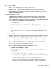
... Start Computer Setup. 2. Do not download or install a BIOS update while the computer is connected to reliable external power using Computer Setup. 1. Do not insert, remove, connect, or disconnect any device, cable, or cord. 1. Select Start > Help and Support > Maintain. 2. Follow the on battery power, docked in an ... to your selection to the hard drive. Updating the BIOS Updated versions of the BIOS may need this path when you are ready to install the update. BIOS version information (also known as ROM date and System BIOS) can be available on the HP Web site are packaged in ...
... Start Computer Setup. 2. Do not download or install a BIOS update while the computer is connected to reliable external power using Computer Setup. 1. Do not insert, remove, connect, or disconnect any device, cable, or cord. 1. Select Start > Help and Support > Maintain. 2. Follow the on battery power, docked in an ... to your selection to the hard drive. Updating the BIOS Updated versions of the BIOS may need this path when you are ready to install the update. BIOS version information (also known as ROM date and System BIOS) can be available on the HP Web site are packaged in ...


