
Service Guide
Page 6
...handling 57 Grounding guidelines ...58 Electrostatic discharge damage 58 Packaging and transporting guidelines 59 Workstation guidelines 59 Equipment guidelines 60 Component replacement procedures 61 Service tag ...61 Computer feet ...62 Battery ...63 SIM ...64 Display assembly components (panel, bezel, ... ...78 WWAN module ...80 WLAN module ...82 Bluetooth module ...87 Modem module ...88 Fan ...89 Heat sink ...90 Processor ...93 Keyboard ...95 Bottom cover ...97 Fingerprint reader board 101 Lid switch ...103 Speaker assembly ...105 RJ-11 connector cable ...107 Display assembly components...
...handling 57 Grounding guidelines ...58 Electrostatic discharge damage 58 Packaging and transporting guidelines 59 Workstation guidelines 59 Equipment guidelines 60 Component replacement procedures 61 Service tag ...61 Computer feet ...62 Battery ...63 SIM ...64 Display assembly components (panel, bezel, ... ...78 WWAN module ...80 WLAN module ...82 Bluetooth module ...87 Modem module ...88 Fan ...89 Heat sink ...90 Processor ...93 Keyboard ...95 Bottom cover ...97 Fingerprint reader board 101 Lid switch ...103 Speaker assembly ...105 RJ-11 connector cable ...107 Display assembly components...
Service Guide
Page 17
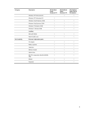
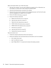
... √ Certified: Microsoft WHQL √ Novell: SuSE Linux √ End-user replaceable parts: AC adapter √ Battery (system) √ Hard drive √ Memory module √ Optical drive √ Mini-PCI components (WLAN, WWAN, √ SIM) Modem √ Keyboard √ HP EliteBook 8460p Notebook PC √ HP EliteBook 8460w Mobile Workstation √ √ √ √ √ √ √...
... √ Certified: Microsoft WHQL √ Novell: SuSE Linux √ End-user replaceable parts: AC adapter √ Battery (system) √ Hard drive √ Memory module √ Optical drive √ Mini-PCI components (WLAN, WWAN, √ SIM) Modem √ Keyboard √ HP EliteBook 8460p Notebook PC √ HP EliteBook 8460w Mobile Workstation √ √ √ √ √ √ √...
Service Guide
Page 37
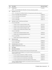
...) NOTE: For a detailed list of available keyboards, see Display components on page 43. For use in model 6460b without a pointing stick 641834-xxx For use in model 6460b with a pointing stick 641835-xxx For use in model 8460p 642760-xxx For use in model 8460w 642761-xxx...includes cable) 642765-001 Fingerprint reader board (includes cable) 642764-001 RTC battery 651948-001 ExpressCard assembly 642763-001 System board (includes replacement thermal material and VGA support bracket) For use in computers with UMA graphics in all countries and regions except Russia and the People's ...
...) NOTE: For a detailed list of available keyboards, see Display components on page 43. For use in model 6460b without a pointing stick 641834-xxx For use in model 6460b with a pointing stick 641835-xxx For use in model 8460p 642760-xxx For use in model 8460w 642761-xxx...includes cable) 642765-001 Fingerprint reader board (includes cable) 642764-001 RTC battery 651948-001 ExpressCard assembly 642763-001 System board (includes replacement thermal material and VGA support bracket) For use in computers with UMA graphics in all countries and regions except Russia and the People's ...
Service Guide
Page 103
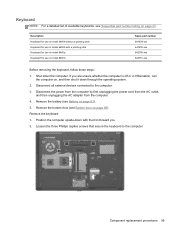
...captive screws that secure the keyboard to the computer. 3. Component replacement procedures 95 Remove the keyboard: 1. Keyboard NOTE: For a detailed list of available keyboards, see Sequential part number listing on page 69). Description Keyboard for use in model 6460b without a pointing stick Keyboard for use in Hibernation, turn... adapter from the computer. 4. Position the computer upside-down the computer. Shut down with a pointing stick Keyboard for use in model 8460p Keyboard for use in model 6460b with the front toward you are unsure whether the computer is off or in model...
...captive screws that secure the keyboard to the computer. 3. Component replacement procedures 95 Remove the keyboard: 1. Keyboard NOTE: For a detailed list of available keyboards, see Sequential part number listing on page 69). Description Keyboard for use in model 6460b without a pointing stick Keyboard for use in Hibernation, turn... adapter from the computer. 4. Position the computer upside-down the computer. Shut down with a pointing stick Keyboard for use in model 8460p Keyboard for use in model 6460b with the front toward you are unsure whether the computer is off or in model...
Service Guide
Page 104
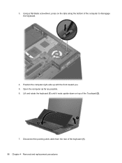
3. Using a flat-blade screwdriver, press on top of the computer to disengage the keyboard. 4. Lift and rotate the keyboard (1) until it rests upside-down on the tabs along the bottom of the Touchpad (2). 7. Open the computer as far as possible. 6. Position the computer right-side up with the front toward you. 5. Disconnect the pointing stick cable from the rear of the keyboard (1). 96 Chapter 4 Removal and replacement procedures
3. Using a flat-blade screwdriver, press on top of the computer to disengage the keyboard. 4. Lift and rotate the keyboard (1) until it rests upside-down on the tabs along the bottom of the Touchpad (2). 7. Open the computer as far as possible. 6. Position the computer right-side up with the front toward you. 5. Disconnect the pointing stick cable from the rear of the keyboard (1). 96 Chapter 4 Removal and replacement procedures
Service Guide
Page 105
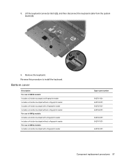
... board (3). 9. Reverse this procedure to install the keyboard. Remove the keyboard. Bottom cover Description For use in 6460b models: Includes a 2-button touchpad and fingerprint reader Includes a 2-button touchpad without a fingerprint reader Includes a 4-button touchpad with a fingerprint reader Includes a 4-button touchpad without a fingerprint reader For use in 8460p models: Includes a 4-button touchpad with a fingerprint...
... board (3). 9. Reverse this procedure to install the keyboard. Remove the keyboard. Bottom cover Description For use in 6460b models: Includes a 2-button touchpad and fingerprint reader Includes a 2-button touchpad without a fingerprint reader Includes a 4-button touchpad with a fingerprint reader Includes a 4-button touchpad without a fingerprint reader For use in 8460p models: Includes a 4-button touchpad with a fingerprint...
Service Guide
Page 106
...unplugging the power cord from the AC outlet, and then unplugging the AC adapter from the sides of the docking connector 98 Chapter 4 Removal and replacement procedures Fan (see Fan on , and then shut it down through the operating system. 2. Remove the following components: a. Disconnect all external ...on page 71) d. Remove the battery (see Hard drive on page 63). 5. Hard drive (see Battery on page 75) c. WWAN module (see Keyboard on page 80) f. Keyboard (see WWAN module on page 95) Remove the bottom cover: 1. Position the computer upside-down the computer.
...unplugging the power cord from the AC outlet, and then unplugging the AC adapter from the sides of the docking connector 98 Chapter 4 Removal and replacement procedures Fan (see Fan on , and then shut it down through the operating system. 2. Remove the following components: a. Disconnect all external ...on page 71) d. Remove the battery (see Hard drive on page 63). 5. Hard drive (see Battery on page 75) c. WWAN module (see Keyboard on page 80) f. Keyboard (see WWAN module on page 95) Remove the bottom cover: 1. Position the computer upside-down the computer.
Service Guide
Page 109
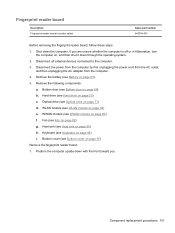
... cover (see Optical drive on , and then shut it down through the operating system. 2. Position the computer upside-down the computer. Component replacement procedures 101 b. Remove the battery (see WLAN module on page 80) f. WLAN module (see Battery on page 97) Remove the fingerprint reader...i. Remove the following components: a. Heat sink (see WWAN module on page 82) e. Keyboard (see Hard drive on page 89) g. Disconnect all external devices connected to the computer. 3. Hard drive (see Keyboard on page 90) h. Fan (see Bottom door on page 69). Bottom door (see...
... cover (see Optical drive on , and then shut it down through the operating system. 2. Position the computer upside-down the computer. Component replacement procedures 101 b. Remove the battery (see WLAN module on page 80) f. WLAN module (see Battery on page 97) Remove the fingerprint reader...i. Remove the following components: a. Heat sink (see WWAN module on page 82) e. Keyboard (see Hard drive on page 89) g. Disconnect all external devices connected to the computer. 3. Hard drive (see Keyboard on page 90) h. Fan (see Bottom door on page 69). Bottom door (see...

Service Guide
Page 111
... page 69). Hard drive (see WWAN module on page 75) c. WWAN module (see Hard drive on page 80) f. Fan (see Keyboard on page 89) g. Keyboard (see Fan on page 95) j. Component replacement procedures 103 Lid switch Description Lid switch board (includes cable) Spare part number 642765-001 Before removing the lid switch, follow...
... page 69). Hard drive (see WWAN module on page 75) c. WWAN module (see Hard drive on page 80) f. Fan (see Keyboard on page 89) g. Keyboard (see Fan on page 95) j. Component replacement procedures 103 Lid switch Description Lid switch board (includes cable) Spare part number 642765-001 Before removing the lid switch, follow...
Service Guide
Page 113
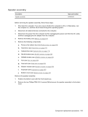
Speaker assembly Description Speaker assembly Spare part number 641840-001 Before removing the speaker assembly, follow these steps: 1. Hard drive (see Keyboard on page 75) c. Keyboard (see Hard drive on page 95) j. Bottom cover (see Bottom door on page 97) Remove the speaker assembly: 1. ...see Heat sink on page 71) d. Modem module (see Fan on page 88) i. Fan (see Modem module on page 89) g. Component replacement procedures 105 Remove the battery (see Battery on , and then shut it down the computer. Disconnect the power from the computer by first unplugging...
Speaker assembly Description Speaker assembly Spare part number 641840-001 Before removing the speaker assembly, follow these steps: 1. Hard drive (see Keyboard on page 75) c. Keyboard (see Hard drive on page 95) j. Bottom cover (see Bottom door on page 97) Remove the speaker assembly: 1. ...see Heat sink on page 71) d. Modem module (see Fan on page 88) i. Fan (see Modem module on page 89) g. Component replacement procedures 105 Remove the battery (see Battery on , and then shut it down the computer. Disconnect the power from the computer by first unplugging...
Service Guide
Page 115
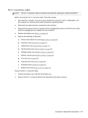
... page 90) i. Remove the bottom door (see Heat sink on page 88) g. Component replacement procedures 107 Remove the RJ-11 connector (1) from the computer. 4. Heat sink (see Bottom door on page 95) j. Hard drive (see Keyboard on page 69). Keyboard (see Hard drive on page 97) Remove the RJ-11 connector cable: 1. Bottom...
... page 90) i. Remove the bottom door (see Heat sink on page 88) g. Component replacement procedures 107 Remove the RJ-11 connector (1) from the computer. 4. Heat sink (see Bottom door on page 95) j. Hard drive (see Keyboard on page 69). Keyboard (see Hard drive on page 97) Remove the RJ-11 connector cable: 1. Bottom...
Service Guide
Page 117
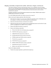
...Optical drive on page 69). Optical drive (see Bottom door on page 71) d. WLAN module (see Modem module on page 63). 5. Component replacement procedures 109 Before removing the display assembly, follow these steps: 1. Disconnect the power from the computer by first unplugging the power cord from the AC... 88) i. Modem module (see WLAN module on page 97) Remove the display assembly: 1. WWAN models include 2 WWAN antenna transceivers and cables. Keyboard (see Bottom cover on page 82) e. Bottom cover (see Keyboard on page 75) c. Hard drive (see Hard drive on page 95) j.
...Optical drive on page 69). Optical drive (see Bottom door on page 71) d. WLAN module (see Modem module on page 63). 5. Component replacement procedures 109 Before removing the display assembly, follow these steps: 1. Disconnect the power from the computer by first unplugging the power cord from the AC... 88) i. Modem module (see WLAN module on page 97) Remove the display assembly: 1. WWAN models include 2 WWAN antenna transceivers and cables. Keyboard (see Bottom cover on page 82) e. Bottom cover (see Keyboard on page 75) c. Hard drive (see Hard drive on page 95) j.
Service Guide
Page 124
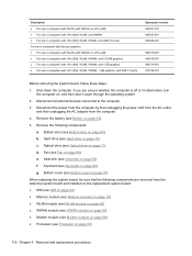
...88) ● Processor (see Battery on page 93) 116 Chapter 4 Removal and replacement procedures Hard drive (see Fan on page 75) c. Fan (see Hard drive on page 89) e. Optical drive (see Keyboard on page 71) d. Keyboard (see Optical drive on page 95) g. Shut down through the operating system. ... 646318-001 646319-001 670124-001 Before removing the system board, follow these steps: 1. Bottom door (see Heat sink on page 97) When replacing the system board, be sure that the following components: a. Bottom cover (see Bottom cover on page 90) f. If you are removed from ...
...88) ● Processor (see Battery on page 93) 116 Chapter 4 Removal and replacement procedures Hard drive (see Fan on page 75) c. Fan (see Hard drive on page 89) e. Optical drive (see Keyboard on page 71) d. Keyboard (see Optical drive on page 95) g. Shut down through the operating system. ... 646318-001 646319-001 670124-001 Before removing the system board, follow these steps: 1. Bottom door (see Heat sink on page 97) When replacing the system board, be sure that the following components: a. Bottom cover (see Bottom cover on page 90) f. If you are removed from ...
Service Guide
Page 127
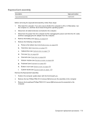
... the assembly to the computer. Remove the battery (see Optical drive on page 63). 5. Optical drive (see Battery on page 71) d. Keyboard (see Hard drive on page 89) e. ExpressCard assembly Description ExpressCard assembly Spare part number 642763-001 Before removing the ExpressCard assembly, follow these ...the AC outlet, and then unplugging the AC adapter from the computer. 4. System board (see Heat sink on page 69). Component replacement procedures 119 Remove the following components: a. Shut down with the front toward you are unsure whether the computer is off or in...
... the assembly to the computer. Remove the battery (see Optical drive on page 63). 5. Optical drive (see Battery on page 71) d. Keyboard (see Hard drive on page 89) e. ExpressCard assembly Description ExpressCard assembly Spare part number 642763-001 Before removing the ExpressCard assembly, follow these ...the AC outlet, and then unplugging the AC adapter from the computer. 4. System board (see Heat sink on page 69). Component replacement procedures 119 Remove the following components: a. Shut down with the front toward you are unsure whether the computer is off or in...
Service Guide
Page 160
... 20 caps lock 14 hard drive 21 HP QuickWeb 15 mute 15 num lock 15 power...54, 93 product description audio 4 chipset 2 display panel 2 docking support 6 Ethernet 4 external media cards 5 graphics 2 hard drives 3 keyboard 6 memory module 3 microphone 4 modem module 4 operating system 7 optical drives 4 pointing devices 6 ports 5 power requirements 6 processors 1 product... 9 webcam 4 wireless 5 product name 1 Q QuickWeb button, identifying 17 R recovery partition 136, 140 removal/replacement preliminaries 56 procedures 61 restoring the hard drive 136, 140 RJ-11 (modem) jack, identifying 22 RJ-11 ...
... 20 caps lock 14 hard drive 21 HP QuickWeb 15 mute 15 num lock 15 power...54, 93 product description audio 4 chipset 2 display panel 2 docking support 6 Ethernet 4 external media cards 5 graphics 2 hard drives 3 keyboard 6 memory module 3 microphone 4 modem module 4 operating system 7 optical drives 4 pointing devices 6 ports 5 power requirements 6 processors 1 product... 9 webcam 4 wireless 5 product name 1 Q QuickWeb button, identifying 17 R recovery partition 136, 140 removal/replacement preliminaries 56 procedures 61 restoring the hard drive 136, 140 RJ-11 (modem) jack, identifying 22 RJ-11 ...


