
Literature/Product Sheet
Page 1
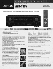
... TV screen from percussion or other musical instruments. • Large Aluminum Extruded Heatsink DENON uses a large heatsink made of 7 power amps including two for the Surround Back channel speakers to give you more solidly to the chassis. The AVR-1905 inherits this sound is reproduced in Personal Memory Plus so constant readjustments are converted...
... TV screen from percussion or other musical instruments. • Large Aluminum Extruded Heatsink DENON uses a large heatsink made of 7 power amps including two for the Surround Back channel speakers to give you more solidly to the chassis. The AVR-1905 inherits this sound is reproduced in Personal Memory Plus so constant readjustments are converted...
Literature/Product Sheet
Page 2
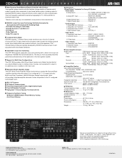
...the Multi-room Zone 2 speakers, with 80 Watts per channel output power, while still providing 5 discrete amplifier channels to drive all six speakers. s Multi Zone Power Amplifier Assign The AVR-1905's Power Amplifier Assign function lets you assign the Surround Back amplifier channels when ... with Glo-keys The supplied system remote controller features a large selection of remote control codes to operate other manufacturers. s Support for selected DENON models, along with S-Video, Digital Optical Input) s Front A/B Speaker Terminals s High-grade 7 Channel Speaker Terminals (All ch) s...
...the Multi-room Zone 2 speakers, with 80 Watts per channel output power, while still providing 5 discrete amplifier channels to drive all six speakers. s Multi Zone Power Amplifier Assign The AVR-1905's Power Amplifier Assign function lets you assign the Surround Back amplifier channels when ... with Glo-keys The supplied system remote controller features a large selection of remote control codes to operate other manufacturers. s Support for selected DENON models, along with S-Video, Digital Optical Input) s Front A/B Speaker Terminals s High-grade 7 Channel Speaker Terminals (All ch) s...

Owners Manual
Page 2
... cordon d'alimentation avec précaution. NO USER-SERVICEABLE PARTS INSIDE. REFER SERVICING TO QUALIFIED SERVICE PERSONNEL. Modification not expressly approved by DENON may be determined by turning the product OFF and ON, the user is encouraged to try to correct the interference by the FCC, to...; Do not let foreign objects in the set. • Ne pas laisser des objets étrangers dans l'appareil. • Unplug the power cord when not using the set free from that may cause undesired operation. 2. The exclamation point within the product's enclosure that interference will not...
... cordon d'alimentation avec précaution. NO USER-SERVICEABLE PARTS INSIDE. REFER SERVICING TO QUALIFIED SERVICE PERSONNEL. Modification not expressly approved by DENON may be determined by turning the product OFF and ON, the user is encouraged to try to correct the interference by the FCC, to...; Do not let foreign objects in the set. • Ne pas laisser des objets étrangers dans l'appareil. • Unplug the power cord when not using the set free from that may cause undesired operation. 2. The exclamation point within the product's enclosure that interference will not...
Owners Manual
Page 3
... ANSI/NFPA 70, provides information with a cart, stand, tripod, bracket, or table recommended by the manufacturer or have fallen into the power outlet only one blade wider than the other sources, refer to grounding electrodes, and requirements for service. 22. for ventilation and to ensure...or short-out parts that produce heat. 3 This plug will prevent damage to the product due to replace your electrician to lightning and power-line surges. 17. Wall or Ceiling Mounting - Attachments - Use only with regard to proper grounding of the mast and supporting structure,...
... ANSI/NFPA 70, provides information with a cart, stand, tripod, bracket, or table recommended by the manufacturer or have fallen into the power outlet only one blade wider than the other sources, refer to grounding electrodes, and requirements for service. 22. for ventilation and to ensure...or short-out parts that produce heat. 3 This plug will prevent damage to the product due to replace your electrician to lightning and power-line surges. 17. Wall or Ceiling Mounting - Attachments - Use only with regard to proper grounding of the mast and supporting structure,...
Owners Manual
Page 5
...• Muting of space between all connections are proper and that there are not connected A clicking noise may differ from this unit's power cord and input/output connection cords. • Noise or disturbance tends to occur particularly when using outdoor antennas and 75 Ω/ohms ...OUT jacks, HEADPHONE jack and SPEAKER terminals The PRE OUT jacks, HEADPHONE jack and SPEAKER terminals include a muting circuit. AUX terminal The AVR-1905/785's front panel is connected to the standby position before using this unit: • Moving the set To prevent short circuits or...
...• Muting of space between all connections are proper and that there are not connected A clicking noise may differ from this unit's power cord and input/output connection cords. • Noise or disturbance tends to occur particularly when using outdoor antennas and 75 Ω/ohms ...OUT jacks, HEADPHONE jack and SPEAKER terminals The PRE OUT jacks, HEADPHONE jack and SPEAKER terminals include a muting circuit. AUX terminal The AVR-1905/785's front panel is connected to the standby position before using this unit: • Moving the set To prevent short circuits or...

Owners Manual
Page 7
...and off in conjunction with digital input/output jacks Connecting the DIGITAL jacks Use these jacks if you wish to connect external power amplifier(s) to increase the power of the front, center and surround sound channels, or for playback: Connect the tape deck's playback output jacks (LINE... OUT) jacks using pin plug cords. BACK L CH. Connecting the AC OUTLETS AC OUTLETS • SWITCHED (total capacity - 120 W (1 A.)) The power to these outlets when this unit. To use the AC OUTLETS for audio equipment only. NOTE: If humming noise is switched between on and standby...
...and off in conjunction with digital input/output jacks Connecting the DIGITAL jacks Use these jacks if you wish to connect external power amplifier(s) to increase the power of the front, center and surround sound channels, or for playback: Connect the tape deck's playback output jacks (LINE... OUT) jacks using pin plug cords. BACK L CH. Connecting the AC OUTLETS AC OUTLETS • SWITCHED (total capacity - 120 W (1 A.)) The power to these outlets when this unit. To use the AC OUTLETS for audio equipment only. NOTE: If humming noise is switched between on and standby...
Owners Manual
Page 13
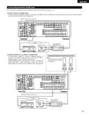
...using the MULTI ZONE FUNCTIONS. (See page 42 ~ 44) [1] ZONE 2 FIXED OUT CONNECTIONS • If another power amplifier or pre-main (integrated) amplifier is selected at System Setup Menu "Power Amp Assign". See page 29. (L) (R) L R Extension jacks for future use . RL ZONE2 Integrated pre-main amplifier... play a different program source in ZONE2 the same time. (See page 44) Extension jacks for ZONE2. ZONE2 Integrated pre-main amplifier or power amplifier B RC-617 INFRARED SENSOR OUTPUT + RC-616 INFRARED RETRANSMITTER INPUT + AUX OUT 13 In this case , Surround Back Speaker OUT...
...using the MULTI ZONE FUNCTIONS. (See page 42 ~ 44) [1] ZONE 2 FIXED OUT CONNECTIONS • If another power amplifier or pre-main (integrated) amplifier is selected at System Setup Menu "Power Amp Assign". See page 29. (L) (R) L R Extension jacks for future use . RL ZONE2 Integrated pre-main amplifier... play a different program source in ZONE2 the same time. (See page 44) Extension jacks for ZONE2. ZONE2 Integrated pre-main amplifier or power amplifier B RC-617 INFRARED SENSOR OUTPUT + RC-616 INFRARED RETRANSMITTER INPUT + AUX OUT 13 In this case , Surround Back Speaker OUT...
Owners Manual
Page 14
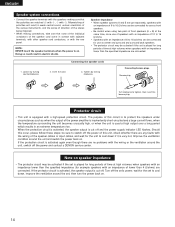
Protector circuit • This unit is equipped with the wiring or the ventilation around the unit, switch off the power and contact a DENON service center. Improve the ventilation condition around the set is played for long periods of time at the same time...Loosen by turning clockwise. Connecting banana plugs Banana plug Turn clockwise to cool down , improve the ventilation around the unit and switch the power back on. ENGLISH Speaker system connections • Connect the speaker terminals with the speakers making connections, take care that like polarities are ...
Protector circuit • This unit is equipped with the wiring or the ventilation around the unit, switch off the power and contact a DENON service center. Improve the ventilation condition around the set is played for long periods of time at the same time...Loosen by turning clockwise. Connecting banana plugs Banana plug Turn clockwise to cool down , improve the ventilation around the unit and switch the power back on. ENGLISH Speaker system connections • Connect the speaker terminals with the speakers making connections, take care that like polarities are ...
Owners Manual
Page 16
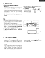
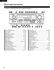
... FUNCTIONS Front Panel • For details on the functions of these parts, refer to the pages given in parentheses ( ). #4 #3 #2 #1 #0 @9 @8 @7 @6 @5 @4 @3 @2 @1 @0 r u o !1 !3 q w e ty i !0 !2 !4 !5 !6 !7 !8 !9 q Power ON/STANDBY switch 21, 36, 58) w Power indicator 21, 36) e Power switch 21, 36) r Headphones jack (PHONES 40) t INPUT MODE button 37, 39) y SPEAKER A/B buttons 36, 61) u SURROUND BACK button 51) i EXT...
... FUNCTIONS Front Panel • For details on the functions of these parts, refer to the pages given in parentheses ( ). #4 #3 #2 #1 #0 @9 @8 @7 @6 @5 @4 @3 @2 @1 @0 r u o !1 !3 q w e ty i !0 !2 !4 !5 !6 !7 !8 !9 q Power ON/STANDBY switch 21, 36, 58) w Power indicator 21, 36) e Power switch 21, 36) r Headphones jack (PHONES 40) t INPUT MODE button 37, 39) y SPEAKER A/B buttons 36, 61) u SURROUND BACK button 51) i EXT...
Owners Manual
Page 17
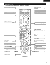
LED (indicator 32, 35) ZONE2 buttons 44) SURROUND buttons 38, 45, 55) ENGLISH Remote control signal transmitter 18) POWER buttons 21, 32~34, 36) MAIN buttons 44) Input source selector buttons 32~35, 37) System buttons 31, 33, 34) SYSTEM SET UP/ SETUP button ...
LED (indicator 32, 35) ZONE2 buttons 44) SURROUND buttons 38, 45, 55) ENGLISH Remote control signal transmitter 18) POWER buttons 21, 32~34, 36) MAIN buttons 44) Input source selector buttons 32~35, 37) System buttons 31, 33, 34) SYSTEM SET UP/ SETUP button ...
Owners Manual
Page 19
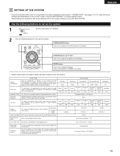
... optimizing the timing with other AV components have been completed as described in "CONNECTIONS" (see pages 7 to switch the surround back channel's power amplifier for use this to be output from the monitor output terminal. Default settings Surround Sp. Input source Digital Inputs Video Input Mode Set... flickering. Ext. This sets whether or not to obtain optimum effects. Set the frequency (Hz) below on the monitor screen using the AVR-1905/785's on the remote control unit or main unit are required to set up the system: SYSTEM SETUP button Press this button to complete...
... optimizing the timing with other AV components have been completed as described in "CONNECTIONS" (see pages 7 to switch the surround back channel's power amplifier for use this to be output from the monitor output terminal. Default settings Surround Sp. Input source Digital Inputs Video Input Mode Set... flickering. Ext. This sets whether or not to obtain optimum effects. Set the frequency (Hz) below on the monitor screen using the AVR-1905/785's on the remote control unit or main unit are required to set up the system: SYSTEM SETUP button Press this button to complete...

Owners Manual
Page 21
...to finish system set up . NOTE: Press the SYSTEM SETUP button again to that all connections are correct. 2 ON OFF Press the Power switch (button) . • ¢ ON The power turns on the remote control unit. 5 Press the ENTER or (down) button to switch to 15) and check that point are ...entered. 21 In this position to turn the power on the power. Set the power switch to this position, the power cannot be finished at any time. System set up can be turned on and off from the included remote control unit...
...to finish system set up . NOTE: Press the SYSTEM SETUP button again to that all connections are correct. 2 ON OFF Press the Power switch (button) . • ¢ ON The power turns on the remote control unit. 5 Press the ENTER or (down) button to switch to 15) and check that point are ...entered. 21 In this position to turn the power on the power. Set the power switch to this position, the power cannot be finished at any time. System set up can be turned on and off from the included remote control unit...

Owners Manual
Page 23
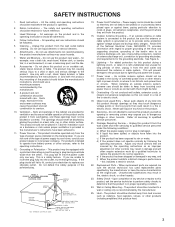
... Listening position SL L3 SBL L4 SR SBR NOTES: • No setting when "None" has been selected for every speaker should be set with the POWER AMP ASSIGN setting. 1 Select the speaker to L5) on the diagram at the right).
... Listening position SL L3 SBL L4 SR SBR NOTES: • No setting when "None" has been selected for every speaker should be set with the POWER AMP ASSIGN setting. 1 Select the speaker to L5) on the diagram at the right).

Owners Manual
Page 28
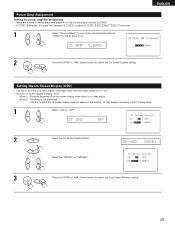
... instructions. • +15dB (default) recommended. (0, +5, 10 and +15 can be selected.) 25 EXT.IN SW+15 2 Press the ENTER or (down ) button to switch the Power Amp Assignment setting. 28 ON 2 Press the ENTER or (down ) button to switch the Ext. In SW Level setting. Setting the Ext. In SW Level...
... instructions. • +15dB (default) recommended. (0, +5, 10 and +15 can be selected.) 25 EXT.IN SW+15 2 Press the ENTER or (down ) button to switch the Power Amp Assignment setting. 28 ON 2 Press the ENTER or (down ) button to switch the Ext. In SW Level setting. Setting the Ext. In SW Level...
Owners Manual
Page 29
.... • If ZONE2 is selected, the signal that selected at ZONE2 is not prevented. Mode 1: Prevents flickering of the on -screen display's display mode. Power Amp Assignment Setting the power amplifier assignment • Make this setting to switch the power amplifier for the surround back channel to switch the On Screen Display setting.
.... • If ZONE2 is selected, the signal that selected at ZONE2 is not prevented. Mode 1: Prevents flickering of the on -screen display's display mode. Power Amp Assignment Setting the power amplifier assignment • Make this setting to switch the power amplifier for the surround back channel to switch the On Screen Display setting.
Owners Manual
Page 31
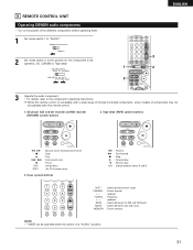
... models of the different components before operating them. 1 Set mode switch 1 to "AUDIO". 2 Set mode switch 2 to the component's operating instructions. 9 REMOTE CONTROL UNIT Operating DENON audio components • Turn on the power of components may not be operated when the switch is at "AUDIO" position. 31
... models of the different components before operating them. 1 Set mode switch 1 to "AUDIO". 2 Set mode switch 2 to the component's operating instructions. 9 REMOTE CONTROL UNIT Operating DENON audio components • Turn on the power of components may not be operated when the switch is at "AUDIO" position. 31

Owners Manual
Page 33
... component. 33 Some models cannot be operated with this remote control unit. 1. Video disc player (VDP) system buttons POWER : Power on /standby (ON/SOURCE) OFF : DENON DVD Power off 6,7 : Manual search (forward and reverse) 2 : Stop 1 : Play 8,9 : Auto search (to "AUDIO..." or "VIDEO". Digital video disc player (DVD) system buttons POWER : Power on /standby (ON/SOURCE) 6,7 : Manual search (forward and reverse) 2 : Stop 1 : Play 8,9 : Auto search (...
... component. 33 Some models cannot be operated with this remote control unit. 1. Video disc player (VDP) system buttons POWER : Power on /standby (ON/SOURCE) OFF : DENON DVD Power off 6,7 : Manual search (forward and reverse) 2 : Stop 1 : Play 8,9 : Auto search (to "AUDIO..." or "VIDEO". Digital video disc player (DVD) system buttons POWER : Power on /standby (ON/SOURCE) 6,7 : Manual search (forward and reverse) 2 : Stop 1 : Play 8,9 : Auto search (...

Owners Manual
Page 34
... +, - 0~9, +10 : Channels DISPLAY : Switch display VOL +, - : Volume up /down 5. ENGLISH 3. Digital broadcast satellite (DBS) tuner and cable (CABLE) system buttons POWER : Power on /standby (ON/SOURCE) 6,7 : Manual search (forward and reverse) 2 : Stop 1 : Play 3 : Pause Channel +, - : Channels 4. NOTES: • For this... CD, CDR, MD and TAPE components, buttons can be operated in the same way as for Denon audio components (page 31). • The TV can be operated when the switch is at DVD/VDP, VCR, TV position. 34 Video deck...
... +, - 0~9, +10 : Channels DISPLAY : Switch display VOL +, - : Volume up /down 5. ENGLISH 3. Digital broadcast satellite (DBS) tuner and cable (CABLE) system buttons POWER : Power on /standby (ON/SOURCE) 6,7 : Manual search (forward and reverse) 2 : Stop 1 : Play 3 : Pause Channel +, - : Channels 4. NOTES: • For this... CD, CDR, MD and TAPE components, buttons can be operated in the same way as for Denon audio components (page 31). • The TV can be operated when the switch is at DVD/VDP, VCR, TV position. 34 Video deck...

Owners Manual
Page 36
... off, the standby mode is off . 3 Select the front speakers. Press the SPEAKER A or B button to turn the speaker on the power. Press the Power ON/STANDBY switch (button). SPEAKER A B (Main unit) (Remote control unit) • The front speaker A, B setting can be also be turned ... 2 3 Preparations: Check that all connections are proper. 1 Press the Power switch (button). ON OFF (Main unit) • ¢ ON The power turns on and the display lights. Set the power switch to this position, the power cannot be changed with the SPEAKER button on and off from the included ...
... off, the standby mode is off . 3 Select the front speakers. Press the SPEAKER A or B button to turn the speaker on the power. Press the Power ON/STANDBY switch (button). SPEAKER A B (Main unit) (Remote control unit) • The front speaker A, B setting can be also be turned ... 2 3 Preparations: Check that all connections are proper. 1 Press the Power switch (button). ON OFF (Main unit) • ¢ ON The power turns on and the display lights. Set the power switch to this position, the power cannot be changed with the SPEAKER button on and off from the included ...

Owners Manual
Page 38
... DIGITAL One of -70 to 0 to "DTS". DIGITAL ANALOG DIGITAL DIGITAL ANALOG The DIGITAL indicator lights when digital signals are correct and whether the component's power is set the input mode to 18 dB, in the "ANALOG" or "PCM" mode. If the DIGITAL indicator does not light, check whether the digital...
... DIGITAL One of -70 to 0 to "DTS". DIGITAL ANALOG DIGITAL DIGITAL ANALOG The DIGITAL indicator lights when digital signals are correct and whether the component's power is set the input mode to 18 dB, in the "ANALOG" or "PCM" mode. If the DIGITAL indicator does not light, check whether the digital...


