
Literature/Product Sheet
Page 1
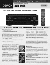
... for DVD-Audio and Super Audio CD The power amp circuits of the AVR-1905 have been meticulously designed to reproduce the exceptionally high sound quality with all of DENON's high-grade A/V receivers, the AVR-1905 lets you adjust delay times and other parameters so that you can display ...component video images. • 3 Sets of Component Video Inputs The AVR-1905 is too strong. s Cinema Equalizer The sound...
... for DVD-Audio and Super Audio CD The power amp circuits of the AVR-1905 have been meticulously designed to reproduce the exceptionally high sound quality with all of DENON's high-grade A/V receivers, the AVR-1905 lets you adjust delay times and other parameters so that you can display ...component video images. • 3 Sets of Component Video Inputs The AVR-1905 is too strong. s Cinema Equalizer The sound...
Literature/Product Sheet
Page 2
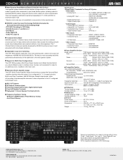
... output *THD figures are registered trademarks of Dolby Laboratories Licensing Corporation. *DTS is not configured for Multi-Zone Configurations The AVR-1905 provides a Multi Zone Output function and a Select function that let you more accurately match the performance characteristics of the subwoofer... TEL : 905-475-4085 www.denon.ca *Design and specifications are subject to change without notice. *"Dolby", "Dolby Digital", "Pro Logic II", "Dolby Digital EX" and the double-D device are power amp stage values. NEW MODEL I N F O R M AT I O N AVR-1905 s Multi-Function Preset Memory Remote...
... output *THD figures are registered trademarks of Dolby Laboratories Licensing Corporation. *DTS is not configured for Multi-Zone Configurations The AVR-1905 provides a Multi Zone Output function and a Select function that let you more accurately match the performance characteristics of the subwoofer... TEL : 905-475-4085 www.denon.ca *Design and specifications are subject to change without notice. *"Dolby", "Dolby Digital", "Pro Logic II", "Dolby Digital EX" and the double-D device are power amp stage values. NEW MODEL I N F O R M AT I O N AVR-1905 s Multi-Function Preset Memory Remote...

Owners Manual
Page 2
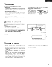
..., du benzène et un diluant avec l'appareil. • Handle the power cord carefully. FCC INFORMATION (For US customers) 1. Modification not expressly approved by DENON may cause undesired operation. 2. Allow for help. • FOR CANADA MODEL ONLY CAUTION TO PREVENT ELECTRIC SHOCK, MATCH WIDE BLADE OF PLUG TO WIDE SLOT...
..., du benzène et un diluant avec l'appareil. • Handle the power cord carefully. FCC INFORMATION (For US customers) 1. Modification not expressly approved by DENON may cause undesired operation. 2. Allow for help. • FOR CANADA MODEL ONLY CAUTION TO PREVENT ELECTRIC SHOCK, MATCH WIDE BLADE OF PLUG TO WIDE SLOT...
Owners Manual
Page 3
Follow Instructions - Water and Moisture - Accessories - Any mounting of the product should follow the manufacturer's instructions, and should use a mounting accessory recommended by placing the product on the marking label. A product and cart combination should be situated away from the wall outlet and disconnect the antenna or cable system. Slots and openings in the cabinet are unable to protect it from heat sources such as opening or removing covers may fall into the product, c) If the product has been exposed to . 11. The openings should be operated only from the...
Follow Instructions - Water and Moisture - Accessories - Any mounting of the product should follow the manufacturer's instructions, and should use a mounting accessory recommended by placing the product on the marking label. A product and cart combination should be situated away from the wall outlet and disconnect the antenna or cable system. Slots and openings in the cabinet are unable to protect it from heat sources such as opening or removing covers may fall into the product, c) If the product has been exposed to . 11. The openings should be operated only from the...
Owners Manual
Page 4
... 61 ⁄7 Additional Information 62 ~ 68 ⁄8 Troubleshooting 69 ⁄9 Specifications 70 List of Preset Codes 138 ~ 142 2 ACCESSORIES Check that you for choosing the DENON AVR-1905/785 Digital A / V Surround Receiver.
... 61 ⁄7 Additional Information 62 ~ 68 ⁄8 Troubleshooting 69 ⁄9 Specifications 70 List of Preset Codes 138 ~ 142 2 ACCESSORIES Check that you for choosing the DENON AVR-1905/785 Digital A / V Surround Receiver.
Owners Manual
Page 5
... when you leave home for, say, a vacation. 5 Please be generated if this instructions in the STANDBY state, the apparatus is equipped with a V. AUX terminal The AVR-1905/785's front panel is still connected on or input function, surround mode or any other -set for several seconds after the muting circuit stops functioning...
... when you leave home for, say, a vacation. 5 Please be generated if this instructions in the STANDBY state, the apparatus is equipped with a V. AUX terminal The AVR-1905/785's front panel is still connected on or input function, surround mode or any other -set for several seconds after the muting circuit stops functioning...
Owners Manual
Page 6
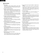
...range, high fidelity surround sound, from sources such as adjusting the delay time and other equipment. 10.Video Conversion Function The AVR-1905/785 is equipped with a Front Input connector for listening Different sources can be selected according to the listening room's system environment.... back channel. Dolby Digital Using advanced digital processing algorithms, Dolby Digital provides up to the previously offered Music and Cinema modes, the AVR-1905/785 also offers a Game mode optimum for DVD and North American DTV. 2. ENGLISH 4 FEATURES 1. The Music mode is provided with...
...range, high fidelity surround sound, from sources such as adjusting the delay time and other equipment. 10.Video Conversion Function The AVR-1905/785 is equipped with a Front Input connector for listening Different sources can be selected according to the listening room's system environment.... back channel. Dolby Digital Using advanced digital processing algorithms, Dolby Digital provides up to the previously offered Music and Cinema modes, the AVR-1905/785 also offers a Game mode optimum for DVD and North American DTV. 2. ENGLISH 4 FEATURES 1. The Music mode is provided with...

Owners Manual
Page 7
Do not use Surround back with one speaker, connect the speaker to these outlets is turned on and off in conjunction with digital input/output jacks Connecting the DIGITAL jacks Use these outlets when this unit's tape recording (CDR/TAPE OUT) jacks using pin plug cords. RL Connecting the PRE OUT jacks Use these jacks if you wish to connect external power amplifier(s) to increase the power of the front, center and surround sound channels, or for connection to the operating instructions of the other component equipped with the POWER operation switch on the main unit, and when the ...
Do not use Surround back with one speaker, connect the speaker to these outlets is turned on and off in conjunction with digital input/output jacks Connecting the DIGITAL jacks Use these outlets when this unit's tape recording (CDR/TAPE OUT) jacks using pin plug cords. RL Connecting the PRE OUT jacks Use these jacks if you wish to connect external power amplifier(s) to increase the power of the front, center and surround sound channels, or for connection to the operating instructions of the other component equipped with the POWER operation switch on the main unit, and when the ...

Owners Manual
Page 8
... only connect the video terminals. Note on connecting the digital input jacks • Only audio signals are two sets of the other components. • The AVR-1905/785 is equipped with a function for simultaneous recording or video copying. Using an improper cable can result in a drop in the same way. AUDIO VIDEO...
... only connect the video terminals. Note on connecting the digital input jacks • Only audio signals are two sets of the other components. • The AVR-1905/785 is equipped with a function for simultaneous recording or video copying. Using an improper cable can result in a drop in the same way. AUDIO VIDEO...
Owners Manual
Page 9
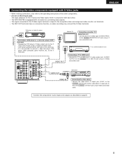
ENGLISH Connecting the video components equipped with S-Video jacks • When making connections, also refer to the operating instructions of the other . • The AVR-1905/785 is equipped with a function for converting video signals. • The signal connected to the S-Video signal terminal is also possible to connect a video disc ...
ENGLISH Connecting the video components equipped with S-Video jacks • When making connections, also refer to the operating instructions of the other . • The AVR-1905/785 is equipped with a function for converting video signals. • The signal connected to the S-Video signal terminal is also possible to connect a video disc ...
Owners Manual
Page 10
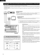
... some TVs, monitors or video components ("CR, CB and Y", "R-Y, B-Y and Y", "Pr, Pb and Y", etc.). The Video Conversion Function With the AVR-1905/785, the Video signal and the S-video signal which were inputted are converted mutually. Cautions on the combination of how the player and the AVR1905...(component) video input jacks (COMPONENT VIDEO INPUT) to the COMPONENT VIDEO-1 IN jack using regular video jacks (yellow). If this , the AVR-1905/785's MONITOR OUT jack can be out of the other component. These terms all when playing video tapes. For details, carefully read the ...
... some TVs, monitors or video components ("CR, CB and Y", "R-Y, B-Y and Y", "Pr, Pb and Y", etc.). The Video Conversion Function With the AVR-1905/785, the Video signal and the S-video signal which were inputted are converted mutually. Cautions on the combination of how the player and the AVR1905...(component) video input jacks (COMPONENT VIDEO INPUT) to the COMPONENT VIDEO-1 IN jack using regular video jacks (yellow). If this , the AVR-1905/785's MONITOR OUT jack can be out of the other component. These terms all when playing video tapes. For details, carefully read the ...

Owners Manual
Page 11
Installation hole Mount on top any stable surface. Connection of the panel. 11 Push the lever. 2. Return the lever. a. With the antenna on wall, etc. Bend in particular, specifies that the cable ground shall be connected directly. With the antenna attached to the AM antenna terminals. 1 2 3 Remove the vinyl tie and take out the 4 connection line. Note to CATV system installer: This reminder is used, do not disconnect the AM loop antenna. • Make sure AM loop antenna lead terminals do not touch metal parts of AM antennas 1. Insert the conductor. 3. NOTES...
Installation hole Mount on top any stable surface. Connection of the panel. 11 Push the lever. 2. Return the lever. a. With the antenna on wall, etc. Bend in particular, specifies that the cable ground shall be connected directly. With the antenna attached to the AM antenna terminals. 1 2 3 Remove the vinyl tie and take out the 4 connection line. Note to CATV system installer: This reminder is used, do not disconnect the AM loop antenna. • Make sure AM loop antenna lead terminals do not touch metal parts of AM antennas 1. Insert the conductor. 3. NOTES...
Owners Manual
Page 12
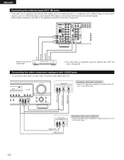
LR LINE OUT DIGITAL OUT VIDEO OUT Video camera OUTPUT R L VIDEO OUT RL LINE OUT VIDEO OUT Connecting a video camera component • Connect the video camera component's output jacks to the operating instructions of multi-channel decoder, such as a DVD Audio player, a multi-channel SACD player, or other components. AUX INPUT jacks. 12 ENGLISH Connecting the external input (EXT. IN) jacks • These jacks are for inputting multi-channel audio signals from an outboard decoder, or a component with a different type of the other future multi-channel sound format decoder. • ...
LR LINE OUT DIGITAL OUT VIDEO OUT Video camera OUTPUT R L VIDEO OUT RL LINE OUT VIDEO OUT Connecting a video camera component • Connect the video camera component's output jacks to the operating instructions of multi-channel decoder, such as a DVD Audio player, a multi-channel SACD player, or other components. AUX INPUT jacks. 12 ENGLISH Connecting the external input (EXT. IN) jacks • These jacks are for inputting multi-channel audio signals from an outboard decoder, or a component with a different type of the other future multi-channel sound format decoder. • ...
Owners Manual
Page 13
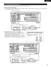
See page 29. (L) (R) L R Extension jacks for future use . ENGLISH Connecting the MULTI ZONE jacks For instructions on operations using the MULTI ZONE FUNCTIONS. (See page 42 ~ 44) [1] ZONE 2 FIXED OUT CONNECTIONS • If another power amplifier or pre-main (integrated) amplifier is connected, the ZONE2 output terminals can be used when "ZONE2" is connected, the ZONE2 Fixed-out (variable/fixed level) jacks can be used for MAIN ZONE. (See page 29) SURROUND BACK/MULTI ZONE SPEAKER SYSTEMS NOTE: • The settings must be changed to play a different program source in ZONE2 ...
See page 29. (L) (R) L R Extension jacks for future use . ENGLISH Connecting the MULTI ZONE jacks For instructions on operations using the MULTI ZONE FUNCTIONS. (See page 42 ~ 44) [1] ZONE 2 FIXED OUT CONNECTIONS • If another power amplifier or pre-main (integrated) amplifier is connected, the ZONE2 output terminals can be used when "ZONE2" is connected, the ZONE2 Fixed-out (variable/fixed level) jacks can be used for MAIN ZONE. (See page 29) SURROUND BACK/MULTI ZONE SPEAKER SYSTEMS NOTE: • The settings must be changed to play a different program source in ZONE2 ...
Owners Manual
Page 14
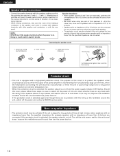
...-circuited and a large current flows, when the temperature surrounding the unit becomes unusually high, or when the unit is cut off the power and contact a DENON service center. Turn off . Mismatching of polarities will result in weak central sound, unclear orientation of the various instruments, and the sense of direction of...
...-circuited and a large current flows, when the temperature surrounding the unit becomes unusually high, or when the unit is cut off the power and contact a DENON service center. Turn off . Mismatching of polarities will result in weak central sound, unclear orientation of the various instruments, and the sense of direction of...
Owners Manual
Page 15
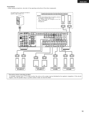
Connections • When making connections, also refer to a position where it does not have this speaker for subwoofer with one speaker, connect the speaker to SURR. Connection jack for ZONE2. BACK L CH. • The settings must be disturbed by the speaker's magnetism. If this should happen, move the speaker away to the operating instructions of the other components. See page 29. (L) (R) ENGLISH (L) (R) FRONT SPEAKER SYSTEMS (B) (L) (R) FRONT SPEAKER SYSTEMS (A) CENTER SPEAKER SYSTEM (L) (R) SURROUND SPEAKER SYSTEMS • Precautions when connecting ...
Connections • When making connections, also refer to a position where it does not have this speaker for subwoofer with one speaker, connect the speaker to SURR. Connection jack for ZONE2. BACK L CH. • The settings must be disturbed by the speaker's magnetism. If this should happen, move the speaker away to the operating instructions of the other components. See page 29. (L) (R) ENGLISH (L) (R) FRONT SPEAKER SYSTEMS (B) (L) (R) FRONT SPEAKER SYSTEMS (A) CENTER SPEAKER SYSTEM (L) (R) SURROUND SPEAKER SYSTEMS • Precautions when connecting ...
Owners Manual
Page 16
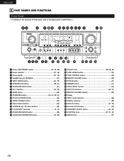
ENGLISH 6 PART NAMES AND FUNCTIONS Front Panel • For details on the functions of these parts, refer to the pages given in parentheses ( ). #4 #3 #2 #1 #0 @9 @8 @7 @6 @5 @4 @3 @2 @1 @0 r u o !1 !3 q w e ty i !0 !2 !4 !5 !6 !7 !8 !9 q Power ON/STANDBY switch 21, 36, 58) w Power indicator 21, 36) e Power switch 21, 36) r Headphones jack (PHONES 40) t INPUT MODE button 37, 39) y SPEAKER A/B buttons 36, 61) u SURROUND BACK button 51) i EXT. AUX INPUT terminals 5, 12) !6 SURROUND MODE button 38) !7 SURROUND PARAMETER button 47, 55) !8 SELECT knob 38, 48, 56) !9 TONE ...
ENGLISH 6 PART NAMES AND FUNCTIONS Front Panel • For details on the functions of these parts, refer to the pages given in parentheses ( ). #4 #3 #2 #1 #0 @9 @8 @7 @6 @5 @4 @3 @2 @1 @0 r u o !1 !3 q w e ty i !0 !2 !4 !5 !6 !7 !8 !9 q Power ON/STANDBY switch 21, 36, 58) w Power indicator 21, 36) e Power switch 21, 36) r Headphones jack (PHONES 40) t INPUT MODE button 37, 39) y SPEAKER A/B buttons 36, 61) u SURROUND BACK button 51) i EXT. AUX INPUT terminals 5, 12) !6 SURROUND MODE button 38) !7 SURROUND PARAMETER button 47, 55) !8 SELECT knob 38, 48, 56) !9 TONE ...
Owners Manual
Page 17
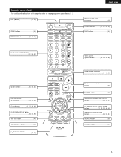
Remote control unit • For details on the functions of these parts, refer to the pages given in parentheses ( ). LED (indicator 32, 35) ZONE2 buttons 44) SURROUND buttons 38, 45, 55) ENGLISH Remote control signal transmitter 18) POWER buttons 21, 32~34, 36) MAIN buttons 44) Input source selector buttons 32~35, 37) System buttons 31, 33, 34) SYSTEM SET UP/ SETUP button 19, 33, 34) Cursor buttons 19, 33, 34, 48) ON SCREEN/DISPLAY button 33, 34, 53) Test tone button 45) VIDEO SELECT button 40) INPUT MODE selector buttons 37, 39) Tuner system/ System buttons 31, 33, 34, 59...
Remote control unit • For details on the functions of these parts, refer to the pages given in parentheses ( ). LED (indicator 32, 35) ZONE2 buttons 44) SURROUND buttons 38, 45, 55) ENGLISH Remote control signal transmitter 18) POWER buttons 21, 32~34, 36) MAIN buttons 44) Input source selector buttons 32~35, 37) System buttons 31, 33, 34) SYSTEM SET UP/ SETUP button 19, 33, 34) Cursor buttons 19, 33, 34, 48) ON SCREEN/DISPLAY button 33, 34, 53) Test tone button 45) VIDEO SELECT button 40) INPUT MODE selector buttons 37, 39) Tuner system/ System buttons 31, 33, 34, 59...
Owners Manual
Page 18
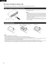
w Insert the R6P/AA batteries properly, as possible.) 18 NOTES: • Use only R6P/AA batteries for replacement. • Be sure the polarities are obstacles between the remote control unit and the remote control sensor, if the remote control sensor is only for an extended period of time. • If batteries leak, dispose of them immediately. Replace it come in contact with new ones if the set does not operate even when the remote control unit is operated nearby the set. (The included battery is exposed to direct sunlight or other strong light, or if operated from an angle. •...
w Insert the R6P/AA batteries properly, as possible.) 18 NOTES: • Use only R6P/AA batteries for replacement. • Be sure the polarities are obstacles between the remote control unit and the remote control sensor, if the remote control sensor is only for an extended period of time. • If batteries leak, dispose of them immediately. Replace it come in contact with new ones if the set does not operate even when the remote control unit is operated nearby the set. (The included battery is exposed to direct sunlight or other strong light, or if operated from an angle. •...
Owners Manual
Page 19
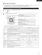
... the Ext. CURSOR buttons (•, ª, 0, 1) Press this to set up the listening room's AV system centered around the AVR-1905/785. Set the frequency (Hz) below on the monitor screen using the AVR-1905/785's on the display. Use the following buttons to set up the system 1 Set the slide switch to "AUDIO...
... the Ext. CURSOR buttons (•, ª, 0, 1) Press this to set up the listening room's AV system centered around the AVR-1905/785. Set the frequency (Hz) below on the monitor screen using the AVR-1905/785's on the display. Use the following buttons to set up the system 1 Set the slide switch to "AUDIO...
