
Literature/Product Sheet
Page 2
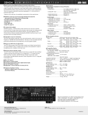
...1 Digital (Optical) Output OPTICAL x 1 • Video Inputs 3 Component Video Input VIDEO1, VIDEO2, VIDEO3 4 Composite Inputs DVD/VDP, TV/DBS, VCR-1, V.AUX(FRONT) 3 S-Video Inputs DVD/VDP, TV/DBS, VCR • Video Outputs 1 Component Video Output MONITOR 2 Composite Outputs VCR, MONITOR 2 S-Video Outputs VCR,...Suite 205 Pine Brook, N.J. 07058-9385 USA TEL: 973-396-0810 www.usa.denon.com DENON CANADA INC. 505 APPLE CREEK BLVD. s Multi Zone Power Amplifier Assign The AVR-1905's Power Amplifier Assign function lets you more accurately match the performance characteristics of delay effects...
...1 Digital (Optical) Output OPTICAL x 1 • Video Inputs 3 Component Video Input VIDEO1, VIDEO2, VIDEO3 4 Composite Inputs DVD/VDP, TV/DBS, VCR-1, V.AUX(FRONT) 3 S-Video Inputs DVD/VDP, TV/DBS, VCR • Video Outputs 1 Component Video Output MONITOR 2 Composite Outputs VCR, MONITOR 2 S-Video Outputs VCR,...Suite 205 Pine Brook, N.J. 07058-9385 USA TEL: 973-396-0810 www.usa.denon.com DENON CANADA INC. 505 APPLE CREEK BLVD. s Multi Zone Power Amplifier Assign The AVR-1905's Power Amplifier Assign function lets you more accurately match the performance characteristics of delay effects...
Owners Manual
Page 5
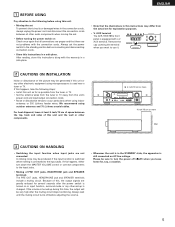
... happens, either turn the power off (£off before adjusting the volume. • Whenever the unit is in a safe place. Always set for , say, a vacation. 5 AUX terminal. Always wait until the muting circuit turns off ) when you want to use it. 2 CAUTIONS ON INSTALLATION Noise or disturbance of this, the output... set. • Before turning the power switch on Check once again that all other electronic equipment using indoor antennas or 300 Ω/ohms feeder wires. AUX terminal The AVR-1905/785's front panel is turned up is turned on AC line voltage.
... happens, either turn the power off (£off before adjusting the volume. • Whenever the unit is in a safe place. Always set for , say, a vacation. 5 AUX terminal. Always wait until the muting circuit turns off ) when you want to use it. 2 CAUTIONS ON INSTALLATION Noise or disturbance of this, the output... set. • Before turning the power switch on Check once again that all other electronic equipment using indoor antennas or 300 Ω/ohms feeder wires. AUX terminal The AVR-1905/785's front panel is turned up is turned on AC line voltage.
Owners Manual
Page 9
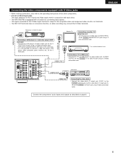
ENGLISH Connecting the video components equipped with S-Video jacks • When making connections, also refer to the operating instructions of the other . • The AVR-1905/785 is equipped with a function for converting video signals. • The signal connected to the S-Video signal terminal is also possible to connect a video disc ... on page 8. 9 VIDEO OUT S-VIDEO OUT IN Video deck VIDEO IN Connecting the video decks • Connect the video deck's S output jack (S-OUT) to the S- AUX jacks. VIDEO DVD IN jack using an S-Video connection cord.
ENGLISH Connecting the video components equipped with S-Video jacks • When making connections, also refer to the operating instructions of the other . • The AVR-1905/785 is equipped with a function for converting video signals. • The signal connected to the S-Video signal terminal is also possible to connect a video disc ... on page 8. 9 VIDEO OUT S-VIDEO OUT IN Video deck VIDEO IN Connecting the video decks • Connect the video deck's S output jack (S-OUT) to the S- AUX jacks. VIDEO DVD IN jack using an S-Video connection cord.
Owners Manual
Page 12
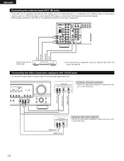
R L R L Front Surround Subwoofer Center Decoder with V.AUX jacks • To connect the video signal, connect using the external input (EXT. Connecting the video component equipped with 6-channel analog output For instructions on ... to the operating instructions of the other future multi-channel sound format decoder. • When making connections, also refer to this unit's V. AUX INPUT jacks. IN) jacks, see page 39. AUX INPUT jacks. 12 IN) jacks • These jacks are for inputting multi-channel audio signals from an outboard decoder, or a component...
R L R L Front Surround Subwoofer Center Decoder with V.AUX jacks • To connect the video signal, connect using the external input (EXT. Connecting the video component equipped with 6-channel analog output For instructions on ... to the operating instructions of the other future multi-channel sound format decoder. • When making connections, also refer to this unit's V. AUX INPUT jacks. IN) jacks, see page 39. AUX INPUT jacks. 12 IN) jacks • These jacks are for inputting multi-channel audio signals from an outboard decoder, or a component...
Owners Manual
Page 13
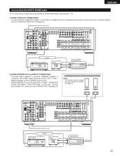
... pre-main amplifier or power amplifier B RC-617 INFRARED SENSOR OUTPUT + RC-616 INFRARED RETRANSMITTER INPUT + AUX OUT 13 RL ZONE2 Integrated pre-main amplifier B RC-617 INFRARED SENSOR OUTPUT + RC-616 INFRARED RETRANSMITTER INPUT + AUX OUT [2] ZONE2 SPEAKER OUT and PREOUT CONNECTIONS • If another pre-main (integrated) amplifier is connected...
... pre-main amplifier or power amplifier B RC-617 INFRARED SENSOR OUTPUT + RC-616 INFRARED RETRANSMITTER INPUT + AUX OUT 13 RL ZONE2 Integrated pre-main amplifier B RC-617 INFRARED SENSOR OUTPUT + RC-616 INFRARED RETRANSMITTER INPUT + AUX OUT [2] ZONE2 SPEAKER OUT and PREOUT CONNECTIONS • If another pre-main (integrated) amplifier is connected...
Owners Manual
Page 16
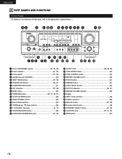
... indicator 21, 36) e Power switch 21, 36) r Headphones jack (PHONES 40) t INPUT MODE button 37, 39) y SPEAKER A/B buttons 36, 61) u SURROUND BACK button 51) i EXT. AUX INPUT terminals 5, 12) !6 SURROUND MODE button 38) !7 SURROUND PARAMETER button 47, 55) !8 SELECT knob 38, 48, 56) !9 TONE DEFEAT button 40) @0 TONE CONTROL button 40...
... indicator 21, 36) e Power switch 21, 36) r Headphones jack (PHONES 40) t INPUT MODE button 37, 39) y SPEAKER A/B buttons 36, 61) u SURROUND BACK button 51) i EXT. AUX INPUT terminals 5, 12) !6 SURROUND MODE button 38) !7 SURROUND PARAMETER button 47, 55) !8 SELECT knob 38, 48, 56) !9 TONE DEFEAT button 40) @0 TONE CONTROL button 40...
Owners Manual
Page 26
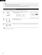
... ENGLISH NOTES: • When you adjust the channel levels while in the TEST TONE mode, the channel level adjustments made will affect all surround modes. AUX cannot be assigned to the input source. • To select the digital input jack 18 COAX CD 2 • To select the input source Select... 26 NOTE: • TUNER and V. Consider this mode a Master Channel Level adjustment mode. • You can adjust the channel levels for each of the AVR-1905/785 for the different input sources. 1 Select the digital input jack to enter the setting and switch the Video Input Mode setting.
... ENGLISH NOTES: • When you adjust the channel levels while in the TEST TONE mode, the channel level adjustments made will affect all surround modes. AUX cannot be assigned to the input source. • To select the digital input jack 18 COAX CD 2 • To select the input source Select... 26 NOTE: • TUNER and V. Consider this mode a Master Channel Level adjustment mode. • You can adjust the channel levels for each of the AVR-1905/785 for the different input sources. 1 Select the digital input jack to enter the setting and switch the Video Input Mode setting.

Owners Manual
Page 41
... Playing one source while recording another (REC OUT mode) 1 Press the ZONE2/REC SELECT button. FUNCTION (Main unit) Display 2 REC CD TUNER AUX DVD / VDP TV / DBS VCR V.AUX CDR / TAPE RECOUT SOURCE NOTES: • Recording sources other than digital inputs selected in the REC OUT mode are also output to the...
... Playing one source while recording another (REC OUT mode) 1 Press the ZONE2/REC SELECT button. FUNCTION (Main unit) Display 2 REC CD TUNER AUX DVD / VDP TV / DBS VCR V.AUX CDR / TAPE RECOUT SOURCE NOTES: • Recording sources other than digital inputs selected in the REC OUT mode are also output to the...

Owners Manual
Page 44
... ZONE2 mode.) (Remote control unit) The main zone output can be selected using the VOLUME + and - FUNCTION (Main unit) Display 2 CD TUNER AUX DVD / VDP TV / DBS ZONE2 VCR V.AUX CDR / TAPE ZONE2 SOURCE NOTES: • The signals of the respective components. 4 To cancel, turn the FUNCTION knob and select the source...
... ZONE2 mode.) (Remote control unit) The main zone output can be selected using the VOLUME + and - FUNCTION (Main unit) Display 2 CD TUNER AUX DVD / VDP TV / DBS ZONE2 VCR V.AUX CDR / TAPE ZONE2 SOURCE NOTES: • The signals of the respective components. 4 To cancel, turn the FUNCTION knob and select the source...


