
Owners Manual
Page 5
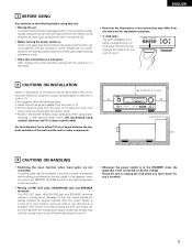
...Install this unit's power cord and input/output connection cords. • Noise or disturbance tends to unplug the cord when you want to the standby position before adjusting the volume. • Whenever the power switch is used near a tuner or TV. If this happens, take the following before..., back and sides of this, the output signals are greatly reduced for several seconds after the muting circuit stops functioning. AUX jacks The AVR-1804/884's front panel is equipped with the connection cords. If the volume is still connected on Check once again that all other components. ...
...Install this unit's power cord and input/output connection cords. • Noise or disturbance tends to unplug the cord when you want to the standby position before adjusting the volume. • Whenever the power switch is used near a tuner or TV. If this happens, take the following before..., back and sides of this, the output signals are greatly reduced for several seconds after the muting circuit stops functioning. AUX jacks The AVR-1804/884's front panel is equipped with the connection cords. If the volume is still connected on Check once again that all other components. ...

Owners Manual
Page 7
...) !3 V. ENGLISH 5 PART NAMES AND FUNCTIONS Front Panel • For details on the functions of these parts, refer to the pages given in parentheses ( ). #4 #3 #2 #1 #0 @9@8@7 @6 @5 @4 @3 @2 @1 @0 !9 e t u o !1 !4 q w r y i !0 !2 !3 !5 !6 !7 !8 q Power ON/STANDBY switch 21, 35, 54) w Headphones jack (PHONES 39) e ZONE2/REC button 40 ~ 42) r SPEAKER A button 35, 57) t SPEAKER B button 35, 57) y SURROUND BACK button 41...
...) !3 V. ENGLISH 5 PART NAMES AND FUNCTIONS Front Panel • For details on the functions of these parts, refer to the pages given in parentheses ( ). #4 #3 #2 #1 #0 @9@8@7 @6 @5 @4 @3 @2 @1 @0 !9 e t u o !1 !4 q w r y i !0 !2 !3 !5 !6 !7 !8 q Power ON/STANDBY switch 21, 35, 54) w Headphones jack (PHONES 39) e ZONE2/REC button 40 ~ 42) r SPEAKER A button 35, 57) t SPEAKER B button 35, 57) y SURROUND BACK button 41...
Owners Manual
Page 10
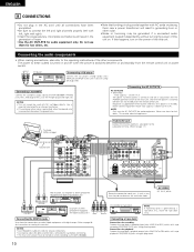
... wire R L RL RL Subwoofer jack Connect the internal amplifier's subwoofer to the subwoofer terminal. (Refer to this unit on when recording via the AVR-1804/884. NOTES: • Use 75 Ω/ohms cable pin cords for coaxial connections. • Use optical cables for hair driers, TVs or ... when the power is at standby. Use a separate head amplifier or step-up transformer. • If humming or other electrical appliances. Connecting the DIGITAL jacks Use these for recording: Connect the tape deck's recording input jacks (LINE IN or REC) to the AVR-1804/884's PHONO jacks, the ...
... wire R L RL RL Subwoofer jack Connect the internal amplifier's subwoofer to the subwoofer terminal. (Refer to this unit on when recording via the AVR-1804/884. NOTES: • Use 75 Ω/ohms cable pin cords for coaxial connections. • Use optical cables for hair driers, TVs or ... when the power is at standby. Use a separate head amplifier or step-up transformer. • If humming or other electrical appliances. Connecting the DIGITAL jacks Use these for recording: Connect the tape deck's recording input jacks (LINE IN or REC) to the AVR-1804/884's PHONO jacks, the ...
Owners Manual
Page 32
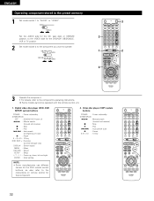
Digital video disc player (DVD, DVD SETUP) system buttons POWER : Power on/standby (ON/SOURCE) OFF : DENON DVD Power off 6,7 : Manual search (forward and reverse) 2 : Stop 1 : Play 8,9 : Auto search (to beginning of track) 3 : Pause 0 ~ 9, +10 : 10 key DISC..., left and right ENTER : Enter setting NOTE: • Some manufacturers use different names for that component. 2. Video disc player (VDP) system buttons POWER : Power on/standby (ON/SOURCE) 6,7 : Manual search (forward and reverse) 2 : Stop 1 : Play 8,9 : Auto search (cue) 3 : Pause 0~9, +10 : 10 key 32 ENGLISH ...
Digital video disc player (DVD, DVD SETUP) system buttons POWER : Power on/standby (ON/SOURCE) OFF : DENON DVD Power off 6,7 : Manual search (forward and reverse) 2 : Stop 1 : Play 8,9 : Auto search (to beginning of track) 3 : Pause 0 ~ 9, +10 : 10 key DISC..., left and right ENTER : Enter setting NOTE: • Some manufacturers use different names for that component. 2. Video disc player (VDP) system buttons POWER : Power on/standby (ON/SOURCE) 6,7 : Manual search (forward and reverse) 2 : Stop 1 : Play 8,9 : Auto search (cue) 3 : Pause 0~9, +10 : 10 key 32 ENGLISH ...
Owners Manual
Page 33
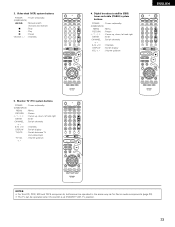
... components, buttons can be operated in the same way as for Denon audio components (page 30). • The TV can be operated when the switch is at DVD/VDP, VCR, TV position. 33 Video deck (VCR) system buttons POWER : Power on /standby (ON/SOURCE) MENU : Menu RETURN : Return D, H, F, G : Cursor up, down, left...
... components, buttons can be operated in the same way as for Denon audio components (page 30). • The TV can be operated when the switch is at DVD/VDP, VCR, TV position. 33 Video deck (VCR) system buttons POWER : Power on /standby (ON/SOURCE) MENU : Menu RETURN : Return D, H, F, G : Cursor up, down, left...

Owners Manual
Page 35
... all connections are required from the time the power operation switch is set and the display turns off . 4 Select the front speakers. Press the ON/STANDBY button on the main unit or ON/SOURCE button on the remote control unit to turn the speaker on. 3 4 2 (Main unit) (Remote control.... Press the SPEAKER A or B button to turn on and the display lights after approximately 1 second. When pressed again, the power turns off, the standby mode is set to the "ON" position until sound is output. 12 OPERATION Before operating 1 Refer to "CONNECTIONS" (pages 10 to 18) and check...
... all connections are required from the time the power operation switch is set and the display turns off . 4 Select the front speakers. Press the ON/STANDBY button on the main unit or ON/SOURCE button on the remote control unit to turn the speaker on. 3 4 2 (Main unit) (Remote control.... Press the SPEAKER A or B button to turn on and the display lights after approximately 1 second. When pressed again, the power turns off, the standby mode is set to the "ON" position until sound is output. 12 OPERATION Before operating 1 Refer to "CONNECTIONS" (pages 10 to 18) and check...
Owners Manual
Page 65
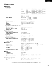
... 0.15% (1kHz) STEREO 0.3% (1kHz) [AM] 520 kHz ~ 1710 kHz 18 µV 2 General Power supply: Power consumption: Maximum external dimensions: Weight: AC 120 V, 60 Hz 4.5 A 1 W Max. (Standby) 434 (W) x 171 (H) x 417 (D) mm (17-3/32" x 6-47/64" x 16-27/64") 11.9 kg (26 lbs 4 oz) 2 Remote control unit (RC-939) Batteries: External dimensions: Weight...
... 0.15% (1kHz) STEREO 0.3% (1kHz) [AM] 520 kHz ~ 1710 kHz 18 µV 2 General Power supply: Power consumption: Maximum external dimensions: Weight: AC 120 V, 60 Hz 4.5 A 1 W Max. (Standby) 434 (W) x 171 (H) x 417 (D) mm (17-3/32" x 6-47/64" x 16-27/64") 11.9 kg (26 lbs 4 oz) 2 Remote control unit (RC-939) Batteries: External dimensions: Weight...


