
Literature/Product Sheet
Page 1
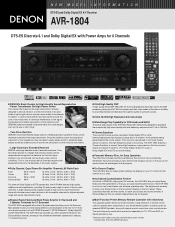
...placed in a design that ensures mostly uniform temperatures throughout the heatsink so that the output transistors for all of DENON's high-grade A/V receiver, the AVR-1804 lets you adjust delay times and other models of this sound is reproduced in the home theater without correction,... placed behind the movie screen. s Multi-Function Preset Memory Remote Controller with Glow-keys The supplied system remote controller features a large selection of remote control codes to operate other components in the DSP processor, placing the AVR-1804 at a higher rank than other parameters so that you can...
...placed in a design that ensures mostly uniform temperatures throughout the heatsink so that the output transistors for all of DENON's high-grade A/V receiver, the AVR-1804 lets you adjust delay times and other models of this sound is reproduced in the home theater without correction,... placed behind the movie screen. s Multi-Function Preset Memory Remote Controller with Glow-keys The supplied system remote controller features a large selection of remote control codes to operate other components in the DSP processor, placing the AVR-1804 at a higher rank than other parameters so that you can...
Owners Manual
Page 4
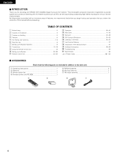
... superb surround sound listening with an immense array of features, we recommend that before proceeding. As this first 9 m Setting up the System 20~29 ⁄1 Remote Control Unit 30~34 ⁄2 Operation 35~40 ⁄3 Multi Zone 41, 42 ⁄4 Surround 43~49 ⁄5 DSP Surround Simulation 50~53 ⁄6 Listening... 57 ⁄9 Additional Information 58~63 ¤0 Troubleshooting 64 ¤1 Specifications 65 List of Preset Codes 128~132 2 ACCESSORIES Check that you for choosing the DENON AVR-1804/884 Digital Surround A/V receiver.
... superb surround sound listening with an immense array of features, we recommend that before proceeding. As this first 9 m Setting up the System 20~29 ⁄1 Remote Control Unit 30~34 ⁄2 Operation 35~40 ⁄3 Multi Zone 41, 42 ⁄4 Surround 43~49 ⁄5 DSP Surround Simulation 50~53 ⁄6 Listening... 57 ⁄9 Additional Information 58~63 ¤0 Troubleshooting 64 ¤1 Specifications 65 List of Preset Codes 128~132 2 ACCESSORIES Check that you for choosing the DENON AVR-1804/884 Digital Surround A/V receiver.

Owners Manual
Page 7
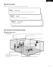
... STATION select buttons 54, 56) @6 BAND button 55) @7 OUTPUT indicator 41) @8 SIGNAL indicator 37) @9 INPUT MODE indicator 37) #0 INPUT MODE button 36, 38, 48) #1 Remote control sensor (REMOTE SENSOR 19) #2 Power operation indicator 35) #3 FUNCTION knob 36, 40) #4 MAIN button 36) 7 IN button 36, 38) o DOLBY/DTS SURROUND button 43, 45, 48...
... STATION select buttons 54, 56) @6 BAND button 55) @7 OUTPUT indicator 41) @8 SIGNAL indicator 37) @9 INPUT MODE indicator 37) #0 INPUT MODE button 36, 38, 48) #1 Remote control sensor (REMOTE SENSOR 19) #2 Power operation indicator 35) #3 FUNCTION knob 36, 40) #4 MAIN button 36) 7 IN button 36, 38) o DOLBY/DTS SURROUND button 43, 45, 48...

Owners Manual
Page 8
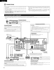
... of these parts, refer to the pages given in parentheses ( ). LED (indicator 31, 34) MULTI ZONE buttons 34, 41, 42) SURROUND buttons 37, 43, 51) Remote control signal transmitter 19) POWER buttons 21, 31~33, 35) MAIN ZONE buttons 34, 42) Input source selector buttons 31~34, 36, 45) System buttons...
... of these parts, refer to the pages given in parentheses ( ). LED (indicator 31, 34) MULTI ZONE buttons 34, 41, 42) SURROUND buttons 37, 43, 51) Remote control signal transmitter 19) POWER buttons 21, 31~33, 35) MAIN ZONE buttons 34, 42) Input source selector buttons 31~34, 36, 45) System buttons...
Owners Manual
Page 9
... must be setup before use. Step 3 (page 20 to setup the Speakers and connecting the components. Step 2 (page 19) Next, insert the batteries into the remote control unit. ENGLISH 7 SETTING UP THE SPEAKER SYSTEMS 2 Speaker system layout Basic system layout • The following is an example of the basic layout for...
... must be setup before use. Step 3 (page 20 to setup the Speakers and connecting the components. Step 2 (page 19) Next, insert the batteries into the remote control unit. ENGLISH 7 SETTING UP THE SPEAKER SYSTEMS 2 Speaker system layout Basic system layout • The following is an example of the basic layout for...
Owners Manual
Page 10
... A.)) The power to the operating instructions of the other noise is generated when the ground wire is switched between on and standby from the remote control unit or power switch. No power is supplied from these outlets is turned on and standby from the... AC cords or placing them for audio equipment only. Connecting a turntable Connect the turntable's output cord to page 26 for audio equipment. Refer to the AVR-1804/884's PHONO jacks, the L (left , right with right). • Insert the plugs securely. Incomplete connections will result in generating hum or other...
... A.)) The power to the operating instructions of the other noise is generated when the ground wire is switched between on and standby from the remote control unit or power switch. No power is supplied from these outlets is turned on and standby from the... AC cords or placing them for audio equipment only. Connecting a turntable Connect the turntable's output cord to page 26 for audio equipment. Refer to the AVR-1804/884's PHONO jacks, the L (left , right with right). • Insert the plugs securely. Incomplete connections will result in generating hum or other...
Owners Manual
Page 19
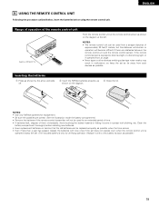
...the leaked material or letting it with a new battery as soon as shown on the diagram. Range of operation of them immediately. NOTES: • The remote control unit can be replaced as quickly as shown on the diagram at the left. w Insert the R6P/AA batteries properly, as possible when the...has passed, replace the batteries with clothing, etc. Replace it come in contact with new ones if the set does not operate even when the remote control unit is operated nearby the set. (The included battery is exposed to direct sunlight or other strong light, or if operated from an ...
...the leaked material or letting it with a new battery as soon as shown on the diagram. Range of operation of them immediately. NOTES: • The remote control unit can be replaced as quickly as shown on the diagram at the left. w Insert the R6P/AA batteries properly, as possible when the...has passed, replace the batteries with clothing, etc. Replace it come in contact with new ones if the set does not operate even when the remote control unit is operated nearby the set. (The included battery is exposed to direct sunlight or other strong light, or if operated from an ...
Owners Manual
Page 20
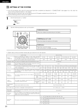
CURSOR buttons (•, ª, 0, 1) Press this change what appears on the display. Set the frequency (Hz) below on the remote control unit or main unit are operated. Front Sp. Input source Digital Inputs CD COAXIAL DVD/VDP TV/DBS OPTICAL 1 OPTICAL 2 VCR-1 OFF VCR-2 OFF ...
CURSOR buttons (•, ª, 0, 1) Press this change what appears on the display. Set the frequency (Hz) below on the remote control unit or main unit are operated. Front Sp. Input source Digital Inputs CD COAXIAL DVD/VDP TV/DBS OPTICAL 1 OPTICAL 2 VCR-1 OFF VCR-2 OFF ...
Owners Manual
Page 21
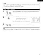
...2 Press the SYSTEM SETUP button to enter the setting. *SYSTEM SET UP NOTE: Please make sure the "AUDIO" position of the slide switch on the remote control unit. 3 Press the ENTER or (down) button to switch to finish system set up . System set up to read small characters on TVs with... the system 1 Check that point are being used. • The system setup is not displayed when "HEADPHONE ONLY" is selected. ENGLISH NOTES: • The AVR-1804/884's on-screen display function is designed for use with high resolution monitor TVs, so it may be finished at any time. NOTE: Press the...
...2 Press the SYSTEM SETUP button to enter the setting. *SYSTEM SET UP NOTE: Please make sure the "AUDIO" position of the slide switch on the remote control unit. 3 Press the ENTER or (down) button to switch to finish system set up . System set up to read small characters on TVs with... the system 1 Check that point are being used. • The system setup is not displayed when "HEADPHONE ONLY" is selected. ENGLISH NOTES: • The AVR-1804/884's on-screen display function is designed for use with high resolution monitor TVs, so it may be finished at any time. NOTE: Press the...

Owners Manual
Page 25
Setting the Test Tone • Use this setting to adjust to that the playback level between the different channel is equal. • From the listening position, listen to the test tones produced from the speakers to adjust the level. • The level can also be adjusted directly from the remote control unit. (For details, see page 43.) 1 Select "Yes". 15 T.TONE
Setting the Test Tone • Use this setting to adjust to that the playback level between the different channel is equal. • From the listening position, listen to the test tones produced from the speakers to adjust the level. • The level can also be adjusted directly from the remote control unit. (For details, see page 43.) 1 Select "Yes". 15 T.TONE
Owners Manual
Page 30
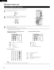
While this remote control. 1. Tuner system buttons 6 : Rewind 7 : Fast-forward 2 : Stop 1 : Forward play 0 : Reverse play A/B : Switch between auto and mono MEMORY : Preset memory NOTE: • TUNER can be ... preset channel range CHANNEL : Preset channel +, - CD player (CD) and CD recorder and MD recorder (CDR/MD) system buttons 2. up /down TUNING : Frequency +, - ENGLISH 11 REMOTE CONTROL UNIT Operating DENON audio components • Turn on the power of components may not be operated with this...
While this remote control. 1. Tuner system buttons 6 : Rewind 7 : Fast-forward 2 : Stop 1 : Forward play 0 : Reverse play A/B : Switch between auto and mono MEMORY : Preset memory NOTE: • TUNER can be ... preset channel range CHANNEL : Preset channel +, - CD player (CD) and CD recorder and MD recorder (CDR/MD) system buttons 2. up /down TUNING : Frequency +, - ENGLISH 11 REMOTE CONTROL UNIT Operating DENON audio components • Turn on the power of components may not be operated with this...
Owners Manual
Page 31
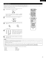
...used to operate components of other manufacturers without using the learning function by setting the preset memory. To avoid accidental operation, cover the remote control unit's transmitting window while setting the preset memory. • Depending on the included list of preset codes. • Some ...manufacturers use the number buttons to the included List of remote control code. ENGLISH Preset memory DENON and other makes of components can be used for some models. 1 Set mode switch 1 to "AUDIO" or "VIDEO". 3...
...used to operate components of other manufacturers without using the learning function by setting the preset memory. To avoid accidental operation, cover the remote control unit's transmitting window while setting the preset memory. • Depending on the included list of preset codes. • Some ...manufacturers use the number buttons to the included List of remote control code. ENGLISH Preset memory DENON and other makes of components can be used for some models. 1 Set mode switch 1 to "AUDIO" or "VIDEO". 3...
Owners Manual
Page 32
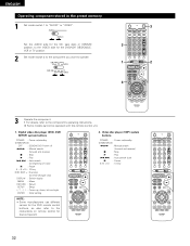
... 8,9 : Auto search (cue) 3 : Pause 0~9, +10 : 10 key 32 Digital video disc player (DVD, DVD SETUP) system buttons POWER : Power on/standby (ON/SOURCE) OFF : DENON DVD Power off 6,7 : Manual search (forward and reverse) 2 : Stop 1 : Play 8,9 : Auto search (to beginning of track) 3 : Pause 0 ~ 9, +10 : 10 key...2 to the component you want to operate. 3 1 2 3 3 Operate the component. • For details, refer to the instructions on remote control for the DVD remote control buttons, so also refer to the component's operating instructions. Some models cannot be operated with this...
... 8,9 : Auto search (cue) 3 : Pause 0~9, +10 : 10 key 32 Digital video disc player (DVD, DVD SETUP) system buttons POWER : Power on/standby (ON/SOURCE) OFF : DENON DVD Power off 6,7 : Manual search (forward and reverse) 2 : Stop 1 : Play 8,9 : Auto search (to beginning of track) 3 : Pause 0 ~ 9, +10 : 10 key...2 to the component you want to operate. 3 1 2 3 3 Operate the component. • For details, refer to the instructions on remote control for the DVD remote control buttons, so also refer to the component's operating instructions. Some models cannot be operated with this...

Owners Manual
Page 35
...8226; ON/STANDBY When the button is set to turn the speaker on. 3 4 2 (Main unit) (Remote control unit) • The front speaker A, B setting can be also be changed with the remote control unit) 3 Turn on the power. Press the ON/STANDBY button on the main unit or ON/SOURCE ...button on the remote control unit to the "ON" position until sound is turned on the remote control unit. ENGLISH 3 4 35 When pressed again, the power turns off . 4 Select the front speakers. This...
...8226; ON/STANDBY When the button is set to turn the speaker on. 3 4 2 (Main unit) (Remote control unit) • The front speaker A, B setting can be also be changed with the remote control unit) 3 Turn on the power. Press the ON/STANDBY button on the main unit or ON/SOURCE ...button on the remote control unit to the "ON" position until sound is turned on the remote control unit. ENGLISH 3 4 35 When pressed again, the power turns off . 4 Select the front speakers. This...
Owners Manual
Page 36
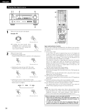
... mode) The signals input to the external decoder input jacks are played without passing through the surround circuitry. AUTO PCM DTS (Main unit) (Remote control unit) 2 Input mode selection function Different input modes can be played. q AUTO (auto mode) In this mode, the types of ...source 11 2 5 3 1 3 5 1 Select the input source to be selected for the selected input source are detected and the program in the AVR-1804/884's surround decoder is selected automatically upon playback. IN to play in the DTS mode. • In some rare cases the noise may be generated...
... mode) The signals input to the external decoder input jacks are played without passing through the surround circuitry. AUTO PCM DTS (Main unit) (Remote control unit) 2 Input mode selection function Different input modes can be played. q AUTO (auto mode) In this mode, the types of ...source 11 2 5 3 1 3 5 1 Select the input source to be selected for the selected input source are detected and the program in the AVR-1804/884's surround decoder is selected automatically upon playback. IN to play in the DTS mode. • In some rare cases the noise may be generated...
Owners Manual
Page 37
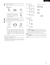
...output if DTS-compatible CDs or LDs are played in steps of these lights, depending on the master volume level display. (Main unit) (Remote control unit) The volume can be heard. 37 NOTE: • The DIGITAL indicator will light when playing CD-ROMs containing data other than ... indicator lights when digital signals are correct and whether the component's power is displayed on the input signal. Example: Stereo (Main unit) (Remote control unit) To select the surround mode while adjusting the surround parameters, tone defeat or tone control, press the surround mode button then operate...
...output if DTS-compatible CDs or LDs are played in steps of these lights, depending on the master volume level display. (Main unit) (Remote control unit) The volume can be heard. 37 NOTE: • The DIGITAL indicator will light when playing CD-ROMs containing data other than ... indicator lights when digital signals are correct and whether the component's power is displayed on the input signal. Example: Stereo (Main unit) (Remote control unit) To select the surround mode while adjusting the surround parameters, tone defeat or tone control, press the surround mode button then operate...
Owners Manual
Page 38
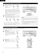
...IN jacks are transmitted directly, resulting in good quality sound. (Main unit) (Remote control unit) 2 STEREO mode Use this mode to achieve good quality 2- Playing audio sources (CDs and DVDs) The AVR-1804/884 is selected, the input signals connected to adjust the tone and achieve the... desired sound while watching 1 images. (Main unit) 1, 2 2 (Remote control unit) 38 IN) jacks 1 Set the external input (EXT. ...
...IN jacks are transmitted directly, resulting in good quality sound. (Main unit) (Remote control unit) 2 STEREO mode Use this mode to achieve good quality 2- Playing audio sources (CDs and DVDs) The AVR-1804/884 is selected, the input signals connected to adjust the tone and achieve the... desired sound while watching 1 images. (Main unit) 1, 2 2 (Remote control unit) 38 IN) jacks 1 Set the external input (EXT. ...
Owners Manual
Page 39
... display. (Main unit) Cancelling simulcast playback. • Select "SOURCE" using headphones. [3] Turning the sound off temporarily (muting) 1 Use this switch to the video input jacks. (Remote control unit) 1 Display 1 1 1 IN=V SOURCE 39
... display. (Main unit) Cancelling simulcast playback. • Select "SOURCE" using headphones. [3] Turning the sound off temporarily (muting) 1 Use this switch to the video input jacks. (Remote control unit) 1 Display 1 1 1 IN=V SOURCE 39
Owners Manual
Page 40
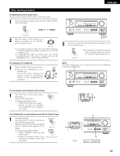
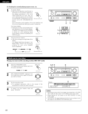
...time an operation is performed, a description of the display. Also, the unit's operating status can be checked during playback by pressing the remote (Remote control unit) control unit's ON SCREEN/DISPLAY button. In addition, the display can be switched to check the unit's operating status while... playing a source by pressing the main unit's DIMMER button repeatedly. (Main unit) BRIGHT MEDIUM OFF DIM (Remote control unit) 21 1 2 Multi-source recording Playing one source while recording another (REC OUT mode) 1 Press the ZONE2/REC button....
...time an operation is performed, a description of the display. Also, the unit's operating status can be checked during playback by pressing the remote (Remote control unit) control unit's ON SCREEN/DISPLAY button. In addition, the display can be switched to check the unit's operating status while... playing a source by pressing the main unit's DIMMER button repeatedly. (Main unit) BRIGHT MEDIUM OFF DIM (Remote control unit) 21 1 2 Multi-source recording Playing one source while recording another (REC OUT mode) 1 Press the ZONE2/REC button....
Owners Manual
Page 41
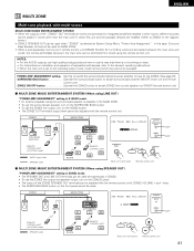
...of separately sold separately room-to-room remote control unit (DENON RC-616, 617 or 618) is S. ZONE2 MAIN ZONE INTEGRATED AMPLIFIER REMOTE CONTROL UNIT with ZONE2 mode : AUDIO signal cable : SPEAKER cable RC-617 AVR-1804/884 FL C FR SW SL RC-616 REMOTE CONTROL UNIT SR SB (Main unit's... front panel) (Remote control unit) (Light) (Light) 2 MULTI ...
...of separately sold separately room-to-room remote control unit (DENON RC-616, 617 or 618) is S. ZONE2 MAIN ZONE INTEGRATED AMPLIFIER REMOTE CONTROL UNIT with ZONE2 mode : AUDIO signal cable : SPEAKER cable RC-617 AVR-1804/884 FL C FR SW SL RC-616 REMOTE CONTROL UNIT SR SB (Main unit's... front panel) (Remote control unit) (Light) (Light) 2 MULTI ...


