
Owners Manual
Page 7
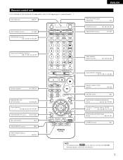
...~30, 32) MAIN ZONE buttons 31, 38) Input source selector buttons 28~31, 33, 42, 43, 45) System buttons 27. 29. 30) SYSTEM SET UP/ SETUP button 19, 26, 29) Cursor buttons 19~26, 29, 30, 40~44, 46) STATUS/DISPLAY button .......(29, 30, 36) Test tone button 40) VIDEO SELECT...~26, 29, 30, 41, 43) SURROUND BACK/RETURN button 29, 30, 45) DIMMER button 36) NOTE: • The shaded buttons do not function with the AVR-1803/883. (Nothing happens when they are pressed.) 7 Remote control unit • For details on the functions of these parts, refer to the pages given in...
...~30, 32) MAIN ZONE buttons 31, 38) Input source selector buttons 28~31, 33, 42, 43, 45) System buttons 27. 29. 30) SYSTEM SET UP/ SETUP button 19, 26, 29) Cursor buttons 19~26, 29, 30, 40~44, 46) STATUS/DISPLAY button .......(29, 30, 36) Test tone button 40) VIDEO SELECT...~26, 29, 30, 41, 43) SURROUND BACK/RETURN button 29, 30, 45) DIMMER button 36) NOTE: • The shaded buttons do not function with the AVR-1803/883. (Nothing happens when they are pressed.) 7 Remote control unit • For details on the functions of these parts, refer to the pages given in...
Owners Manual
Page 8
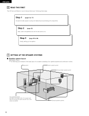
ENGLISH 6 READ THIS FIRST This AV Surround Receiver must be setup before use. Step 3 (page 19 to setup the Speakers and connecting the components. Step 2 (page 18) Next, insert the batteries into the remote control unit. Following these at the sides of the ...
ENGLISH 6 READ THIS FIRST This AV Surround Receiver must be setup before use. Step 3 (page 19 to setup the Speakers and connecting the components. Step 2 (page 18) Next, insert the batteries into the remote control unit. Following these at the sides of the ...

Owners Manual
Page 12
... connections, also refer to the operating instructions of the other component. 12 These terms all refer to component video color difference output. • At SYSTEM SETUP, the component video input terminal can be indicated differently on some TVs, monitors or video components ("CR, CB and Y", "R-Y, B-Y and Y", "Pr, Pb and Y", etc.). For...
... connections, also refer to the operating instructions of the other component. 12 These terms all refer to component video color difference output. • At SYSTEM SETUP, the component video input terminal can be indicated differently on some TVs, monitors or video components ("CR, CB and Y", "R-Y, B-Y and Y", "Pr, Pb and Y", etc.). For...

Owners Manual
Page 19
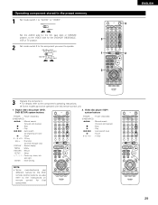
... the composition of the signals output from the speakers and the frequency response. In SW Level = +15 dB NOTE: • The system setup is not displayed when "HEADPHONE ONLY" is for optimizing the timing with other AV components have been completed as described in "CONNECTIONS" (see ...up the system: 1 Set the slide switch to "AUDIO". 2 Use the following buttons to set up the system: SYSTEM SETUP button Press this to display the system setup on the display. These settings are produced from the speakers and subwoofer according to the listening position. CURSOR buttons (•, &#...
... the composition of the signals output from the speakers and the frequency response. In SW Level = +15 dB NOTE: • The system setup is not displayed when "HEADPHONE ONLY" is for optimizing the timing with other AV components have been completed as described in "CONNECTIONS" (see ...up the system: 1 Set the slide switch to "AUDIO". 2 Use the following buttons to set up the system: SYSTEM SETUP button Press this to display the system setup on the display. These settings are produced from the speakers and subwoofer according to the listening position. CURSOR buttons (•, &#...

Owners Manual
Page 20
...main unit or the POWER button on the remote control unit to turn on the power. (Main unit) (Remote control unit) 2 Press the SYSTEM SETUP button to enter the setting. *SYSTEM SET UP NOTE: Please make sure the "AUDIO" position of the slide switch on the remote control unit. 3...) 1 FRONT LARGE LARGE SMALL Press the ENTER or (left ) and (right) buttons to select your surround speaker type. (Initial) 3 SURR. NOTE: Press the SYSTEM SETUP button again to finish system set up to that all the components are entered. NOTE: • When "Small" has been selected for the front speakers...
...main unit or the POWER button on the remote control unit to turn on the power. (Main unit) (Remote control unit) 2 Press the SYSTEM SETUP button to enter the setting. *SYSTEM SET UP NOTE: Please make sure the "AUDIO" position of the slide switch on the remote control unit. 3...) 1 FRONT LARGE LARGE SMALL Press the ENTER or (left ) and (right) buttons to select your surround speaker type. (Initial) 3 SURR. NOTE: Press the SYSTEM SETUP button again to finish system set up to that all the components are entered. NOTE: • When "Small" has been selected for the front speakers...

Owners Manual
Page 22
... with a frequency below the crossover frequency is cut, and the cut bass sound is to be little interference of the low frequency range in the setup. Assignment of low frequency signal range - • The signals produced from the subwoofer channel are LFE signals (during playback of Dolby Digital or DTS signals...
... with a frequency below the crossover frequency is cut, and the cut bass sound is to be little interference of the low frequency range in the setup. Assignment of low frequency signal range - • The signals produced from the subwoofer channel are LFE signals (during playback of Dolby Digital or DTS signals...

Owners Manual
Page 26
...'s operating instructions. • +15dB (default) recommended. (0, +5, 10 and +15 can be selected.) After setting up the system 1 Press the SYSTEM SETUP button to finish system set up . This completes the system setup operations. In SW Level setting. In terminal. 1 Use the (left ) button (right) button (down ) button if you want to start...
...'s operating instructions. • +15dB (default) recommended. (0, +5, 10 and +15 can be selected.) After setting up the system 1 Press the SYSTEM SETUP button to finish system set up . This completes the system setup operations. In SW Level setting. In terminal. 1 Use the (left ) button (right) button (down ) button if you want to start...
Owners Manual
Page 29
... 1 : Play 8,9 : Auto search (to beginning of track) 3 : Pause 0 ~ 9, +10 : 10 key skip + : Disc skip (for DVD changer only) DISPLAY : Switch display MENU : Menu RETURN : Return SETUP : Setup D, H, F, G : Cursor up, down, left and right ENTER : Enter setting POWER : Power on remote control for that component. 29 Operating component stored in the preset memory...
... 1 : Play 8,9 : Auto search (to beginning of track) 3 : Pause 0 ~ 9, +10 : 10 key skip + : Disc skip (for DVD changer only) DISPLAY : Switch display MENU : Menu RETURN : Return SETUP : Setup D, H, F, G : Cursor up, down, left and right ENTER : Enter setting POWER : Power on remote control for that component. 29 Operating component stored in the preset memory...

Owners Manual
Page 34
... level is adjusted to 18 dB, in the "ANALOG" or "PCM" mode. If the DIGITAL indicator does not light, check whether the digital input component setup (page 24) and connections are being input properly. Press the SURROUND MODE button, then turn the SELECT knob. NOTE: • The DIGITAL indicator will light...
... level is adjusted to 18 dB, in the "ANALOG" or "PCM" mode. If the DIGITAL indicator does not light, check whether the digital input component setup (page 24) and connections are being input properly. Press the SURROUND MODE button, then turn the SELECT knob. NOTE: • The DIGITAL indicator will light...

Owners Manual
Page 47
... off with reduced dynamic range). (This only works when playing program sources recorded in the soundtrack (but with the subwoofer peak limit level setting (system setup menu), adjust the level as necessary. Dolby Digital: -10 dB to OFF for correct DTS playback. NOTE: This operation can be set for all of...
... off with reduced dynamic range). (This only works when playing program sources recorded in the soundtrack (but with the subwoofer peak limit level setting (system setup menu), adjust the level as necessary. Dolby Digital: -10 dB to OFF for correct DTS playback. NOTE: This operation can be set for all of...


