Information Update
Page 7
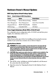
... the safety instructions that is not authorized by Dell is 2+1. Installing Memory Modules WARNING: The memory modules are hot to cool before handling them. You should only perform troubleshooting and simple repairs as authorized in your system has a memory riser as directed by the card edges and avoid... touching the components on the memory module. System Memory Follow the procedure given below for some time after the system has been powered ...
... the safety instructions that is not authorized by Dell is 2+1. Installing Memory Modules WARNING: The memory modules are hot to cool before handling them. You should only perform troubleshooting and simple repairs as authorized in your system has a memory riser as directed by the card edges and avoid... touching the components on the memory module. System Memory Follow the procedure given below for some time after the system has been powered ...
Information Update
Page 8
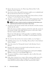
... main System Setup screen. 13 The system should have memory modules installed. 3 Remove the memory risers. When the memory module is properly seated in their sockets. 8 Information Update Repeat step 2 through step 7 of the memory modules may not be installed properly. See Figure 2. 9 Install the memory risers. See "Installing a Memory Riser" in the Hardware Owner's Manual. 8 Press the four...
... main System Setup screen. 13 The system should have memory modules installed. 3 Remove the memory risers. When the memory module is properly seated in their sockets. 8 Information Update Repeat step 2 through step 7 of the memory modules may not be installed properly. See Figure 2. 9 Install the memory risers. See "Installing a Memory Riser" in the Hardware Owner's Manual. 8 Press the four...

Information Update
Page 9
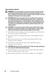
Figure 1. 15 Run the system memory test in the Hardware Owner's Manual. See "Running the Embedded System Diagnostics" in the system diagnostics. Installing and Removing a Memory Module 2 3 1 4 6 1 release tabs (2) 3 memory riser 5 card guide 5 2 handle 4 release button 6 memory-riser connector Information Update 9
Figure 1. 15 Run the system memory test in the Hardware Owner's Manual. See "Running the Embedded System Diagnostics" in the system diagnostics. Installing and Removing a Memory Module 2 3 1 4 6 1 release tabs (2) 3 memory riser 5 card guide 5 2 handle 4 release button 6 memory-riser connector Information Update 9
Information Update
Page 10
...done by the online or telephone service and support team. See "Removing a Memory Riser" in the Hardware Owner's Manual. 4 Press the tabs in the Hardware Owner's Manual. 3 Remove the memory risers. Remove memory-module blanks only if you intend to servicing that came with the product. See...Read and follow the safety instructions that is not authorized by Dell is not occupied. Removing Memory Modules WARNING: The memory modules are hot to touch the middle of the memory module. 5 Press down . Handle the memory modules by your product documentation, or as authorized in your ...
...done by the online or telephone service and support team. See "Removing a Memory Riser" in the Hardware Owner's Manual. 4 Press the tabs in the Hardware Owner's Manual. 3 Remove the memory risers. Remove memory-module blanks only if you intend to servicing that came with the product. See...Read and follow the safety instructions that is not authorized by Dell is not occupied. Removing Memory Modules WARNING: The memory modules are hot to touch the middle of the memory module. 5 Press down . Handle the memory modules by your product documentation, or as authorized in your ...
Information Update
Page 11
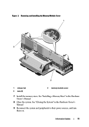
Information Update 11 See "Closing the System" in the Hardware Owner's Manual. 8 Close the system. See "Installing a Memory Riser" in the Hardware Owner's Manual. 9 Reconnect the system and peripherals to their power sources, and turn them on. Removing and Installing the Memory Module Cover 1 3 2 1 release tab 3 tabs (4) 2 memory module cover 7 Install the memory risers. Figure 2.
Information Update 11 See "Closing the System" in the Hardware Owner's Manual. 8 Close the system. See "Installing a Memory Riser" in the Hardware Owner's Manual. 9 Reconnect the system and peripherals to their power sources, and turn them on. Removing and Installing the Memory Module Cover 1 3 2 1 release tab 3 tabs (4) 2 memory module cover 7 Install the memory risers. Figure 2.
Getting Started Guide
Page 10
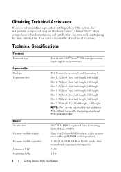
Obtaining Technical Assistance If you do not understand a procedure in all locations. See www.dell.com/training for more information. This service may not be expanded to eight-core processors) Expansion Bus Bus type Expansion slots PCI Express Generation 1 and... capacities Minimum RAM Maximum RAM 1067 MHz DDR3 registered Error Correcting Code (ECC) DIMMs Sixty four 240-pin DIMM sockets (eight memory risers with eight DIMM sockets per riser) 1 GB, 2 GB, 4 GB, 8 GB, or 16 GB (single, dual, or quad-rank dependent on capacity) 4 GB 1 TB 8 Getting Started With Your System Technical ...
Obtaining Technical Assistance If you do not understand a procedure in all locations. See www.dell.com/training for more information. This service may not be expanded to eight-core processors) Expansion Bus Bus type Expansion slots PCI Express Generation 1 and... capacities Minimum RAM Maximum RAM 1067 MHz DDR3 registered Error Correcting Code (ECC) DIMMs Sixty four 240-pin DIMM sockets (eight memory risers with eight DIMM sockets per riser) 1 GB, 2 GB, 4 GB, 8 GB, or 16 GB (single, dual, or quad-rank dependent on capacity) 4 GB 1 TB 8 Getting Started With Your System Technical ...

Hardware Owner's Manual
Page 27
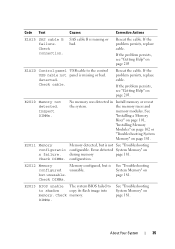
... range. See "Troubleshooting System Cooling Problems" on page 190. If the problem persists, see "Getting Help" on page 203. E1234 Memory Riser # power failure. Contact Support. Check or add PSUs. E1245 CPU # VIO Regulator failure. Contact support. Check fan. Code Text Causes Corrective...Processor voltage regulator failed. RPM of specified fan is outside of the intended operating range. About Your System 27 Reseat the I/O riser. Reseat the memory riser. If the problem persists, see "Getting Help" on page 203. E1244 Embedded 10Gb Insufficient standby power NICs for 10 Gb...
... range. See "Troubleshooting System Cooling Problems" on page 190. If the problem persists, see "Getting Help" on page 203. E1234 Memory Riser # power failure. Contact Support. Check or add PSUs. E1245 CPU # VIO Regulator failure. Contact support. Check fan. Code Text Causes Corrective...Processor voltage regulator failed. RPM of specified fan is outside of the intended operating range. About Your System 27 Reseat the I/O riser. Reseat the memory riser. If the problem persists, see "Getting Help" on page 203. E1244 Embedded 10Gb Insufficient standby power NICs for 10 Gb...
Hardware Owner's Manual
Page 35
... Your System 35 Reseat the cable. detected. Check cable. E2011 Memory configuratio n failure. configuration. E2012 Memory configured Memory configured, but is not See "Troubleshooting configurable. See "Installing a Memory Riser" on page 101, "Installing Memory Modules" on page 102 or "Troubleshooting System Memory" on page 181. If the problem persists, see "Getting Help" on page 203. Check DIMMs...
... Your System 35 Reseat the cable. detected. Check cable. E2011 Memory configuratio n failure. configuration. E2012 Memory configured Memory configured, but is not See "Troubleshooting configurable. See "Installing a Memory Riser" on page 101, "Installing Memory Modules" on page 102 or "Troubleshooting System Memory" on page 181. If the problem persists, see "Getting Help" on page 203. Check DIMMs...
Hardware Owner's Manual
Page 47
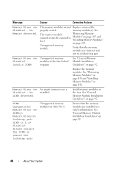
... are installed in a valid configuration. DDR training failure Memory Riser disabled - Message Causes Corrective Actions Memory Riser disabled - The memory riser connector is not properly seated. Ensure that there are clean. Memory Riser disabled - Memory Buffer communication error. Reseat the memory riser(s). Memory Riser disabled MemBIST timeout. Memory riser disabled - About Your System 47 The memory riser connector or the processor socket may be exposed to Modules...
... are installed in a valid configuration. DDR training failure Memory Riser disabled - Message Causes Corrective Actions Memory Riser disabled - The memory riser connector is not properly seated. Ensure that there are clean. Memory Riser disabled - Memory Buffer communication error. Reseat the memory riser(s). Memory Riser disabled MemBIST timeout. Memory riser disabled - About Your System 47 The memory riser connector or the processor socket may be exposed to Modules...
Hardware Owner's Manual
Page 48
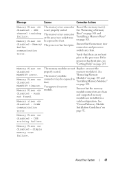
... page 92. 48 About Your System Message Causes Corrective Actions Memory Riser disabled - Memory Riser An empty memory riser is disabled - No Memory detected. "Installing Memory Modules" on page 92. Replace the memory modules. No installed. The memory modules are installed in a locked step pair. modules in the riser. See "General Memory Module Installation Guidelines" on page 105 and dust. Verify that...
... page 92. 48 About Your System Message Causes Corrective Actions Memory Riser disabled - Memory Riser An empty memory riser is disabled - No Memory detected. "Installing Memory Modules" on page 92. Replace the memory modules. No installed. The memory modules are installed in a locked step pair. modules in the riser. See "General Memory Module Installation Guidelines" on page 105 and dust. Verify that...

Hardware Owner's Manual
Page 49
.... Lockstep Pair DIMM disabled. See Locstep Pair DIMM The memory module "Removing Memory disabled. module connectors are not Replace or reseat the Memory riser properly seated. Please replace the lockstep pair with matching DIMM(s). DDR training Error: Memory riser DIMM Memory riser lockstep pair disabled. remove the Ensure that the memory modules match for a locked step pair. About Your...
.... Lockstep Pair DIMM disabled. See Locstep Pair DIMM The memory module "Removing Memory disabled. module connectors are not Replace or reseat the Memory riser properly seated. Please replace the lockstep pair with matching DIMM(s). DDR training Error: Memory riser DIMM Memory riser lockstep pair disabled. remove the Ensure that the memory modules match for a locked step pair. About Your...

Hardware Owner's Manual
Page 50
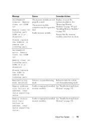
... slot. Please ensure each lockstep pair is installed correctly. 50 About Your System DDR Channel Disabled. Memory riser lockstep pair DIMM disabled. See "General Memory Module Installation Guidelines" on slots 5 and 6. Memory riser lockstep pair DIMM disabled. Ensure that the memory modules are installed on slots 1 and 2 or on page 92. Please populate DIMM(s) with largest...
... slot. Please ensure each lockstep pair is installed correctly. 50 About Your System DDR Channel Disabled. Memory riser lockstep pair DIMM disabled. See "General Memory Module Installation Guidelines" on slots 5 and 6. Memory riser lockstep pair DIMM disabled. Ensure that the memory modules are installed on slots 1 and 2 or on page 92. Please populate DIMM(s) with largest...
Hardware Owner's Manual
Page 51
... address, read value expecting value. Ensure that the memory module connectors are not Replace or reseat the properly seated. Manufacturing mode detected. Memory" on page 181. Message Causes Corrective Actions DellMemBIST timeout: Memory riser DIMM Memory riser lockstep pair DIMM disabled. The memory modules are clean. Faulty memory module. Memory address line failure at address, read value expecting value...
... address, read value expecting value. Ensure that the memory module connectors are not Replace or reseat the properly seated. Manufacturing mode detected. Memory" on page 181. Message Causes Corrective Actions DellMemBIST timeout: Memory riser DIMM Memory riser lockstep pair DIMM disabled. The memory modules are clean. Faulty memory module. Memory address line failure at address, read value expecting value...
Hardware Owner's Manual
Page 86
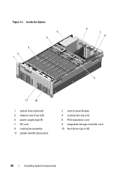
Inside the System 5 4 3 2 1 6 7 8 9 11 10 1 optical drive (optional) 3 memory risers (up to 8) 5 power supply bays (4) 7 I/O card 9 cooling fan assembly 11 system identification panel 2 control panel display 4 cooling fans (up to 6) 6 PCIe expansion card 8 integrated storage controller card 10 hard drives (up to 16) 86 Installing System Components Figure 3-1.
Inside the System 5 4 3 2 1 6 7 8 9 11 10 1 optical drive (optional) 3 memory risers (up to 8) 5 power supply bays (4) 7 I/O card 9 cooling fan assembly 11 system identification panel 2 control panel display 4 cooling fans (up to 6) 6 PCIe expansion card 8 integrated storage controller card 10 hard drives (up to 16) 86 Installing System Components Figure 3-1.

Hardware Owner's Manual
Page 91
...system varies according to the sizes of memory modules being used. System Memory Your system supports DDR3 registered DIMMs (RDIMMs). Figure 3-5. NOTE: Depending on the screen. Each memory riser has eight DIMM sockets arranged into four sets of memory installed, the system may take up... to display video on the amount of two risers per processor. Single-rank, dual-rank, and quadrank RDIMMs of sizes...
...system varies according to the sizes of memory modules being used. System Memory Your system supports DDR3 registered DIMMs (RDIMMs). Figure 3-5. NOTE: Depending on the screen. Each memory riser has eight DIMM sockets arranged into four sets of memory installed, the system may take up... to display video on the amount of two risers per processor. Single-rank, dual-rank, and quadrank RDIMMs of sizes...

Hardware Owner's Manual
Page 92
... the size N+/-1. • The memory speed depends on the memory mode selected. The memory speeds are installed in both the risers. Two memory risers are installed, they operate at the speed of the slowest installed memory module(s). General Memory Module Installation Guidelines To ensure optimal ... following general guidelines when configuring your system from starting and producing any video output. • All populated memory risers must have identical configurations. The mixed memory configurations must be mixed (for example, 2 GB and 4 GB), but all populated channels must have ...
... the size N+/-1. • The memory speed depends on the memory mode selected. The memory speeds are installed in both the risers. Two memory risers are installed, they operate at the speed of the slowest installed memory module(s). General Memory Module Installation Guidelines To ensure optimal ... following general guidelines when configuring your system from starting and producing any video output. • All populated memory risers must have identical configurations. The mixed memory configurations must be mixed (for example, 2 GB and 4 GB), but all populated channels must have ...
Hardware Owner's Manual
Page 95
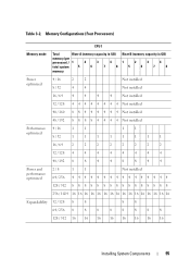
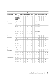
... Configurations (Four Processors) CPU 1 Memory mode Total Riser A (memory capacity in GB) memory (per processor) / 1 2 3 4 total system 5 6 7 8 memory Riser B (memory capacity in GB) 1 2 3 4 5 6 7 8 Power 4 / 16 2 2 optimized 8 / 32 4 4 Not installed Not installed 16 / 64 4 4 4 4 Not installed 32 / 128 4 4 4 4 4 4 4 4 Not installed 40 / 160 8 8 4 4 4 4 4 4 Not installed 48 / 192 8 8 8 8 4 4 4 4 ...
... Configurations (Four Processors) CPU 1 Memory mode Total Riser A (memory capacity in GB) memory (per processor) / 1 2 3 4 total system 5 6 7 8 memory Riser B (memory capacity in GB) 1 2 3 4 5 6 7 8 Power 4 / 16 2 2 optimized 8 / 32 4 4 Not installed Not installed 16 / 64 4 4 4 4 Not installed 32 / 128 4 4 4 4 4 4 4 4 Not installed 40 / 160 8 8 4 4 4 4 4 4 Not installed 48 / 192 8 8 8 8 4 4 4 4 ...

Hardware Owner's Manual
Page 96
CPU 2 Memory mode Total Riser A (memory capacity in GB) memory (per processor) / 1 2 3 4 total system 5 6 7 8 memory Riser B (memory capacity in GB) 1 2 3 4 5 6 7 8 Power 4 / 16 2 2 optimized 8 / 32 4 4 Not installed Not installed 16 / 64 4 4 4 4 Not installed 32 / 128 4 4 4 4 4 4 4 4 Not installed 40 / 160 8 8 4 4 4 4 4 4 Not installed 48 / 192 8 8 8 8 4 4 4 4 ...
CPU 2 Memory mode Total Riser A (memory capacity in GB) memory (per processor) / 1 2 3 4 total system 5 6 7 8 memory Riser B (memory capacity in GB) 1 2 3 4 5 6 7 8 Power 4 / 16 2 2 optimized 8 / 32 4 4 Not installed Not installed 16 / 64 4 4 4 4 Not installed 32 / 128 4 4 4 4 4 4 4 4 Not installed 40 / 160 8 8 4 4 4 4 4 4 Not installed 48 / 192 8 8 8 8 4 4 4 4 ...
Hardware Owner's Manual
Page 97
CPU 3 Memory mode Total Riser A (memory capacity in GB) memory (per processor) / 1 2 3 4 total system 5 6 7 8 memory Riser B (memory capacity in GB) 1 2 3 4 5 6 7 8 Power 4 / 16 2 2 optimized 8 / 32 4 4 Not installed Not installed 16 / 64 4 4 4 4 Not installed 32 / 128 4 4 4 4 4 4 4 4 Not installed 40 / 160 8 8 4 4 4 4 4 4 Not installed 48 / 192 8 8 8 8 4 4 4 4 ...
CPU 3 Memory mode Total Riser A (memory capacity in GB) memory (per processor) / 1 2 3 4 total system 5 6 7 8 memory Riser B (memory capacity in GB) 1 2 3 4 5 6 7 8 Power 4 / 16 2 2 optimized 8 / 32 4 4 Not installed Not installed 16 / 64 4 4 4 4 Not installed 32 / 128 4 4 4 4 4 4 4 4 Not installed 40 / 160 8 8 4 4 4 4 4 4 Not installed 48 / 192 8 8 8 8 4 4 4 4 ...

Hardware Owner's Manual
Page 98
CPU 4 Memory mode Total Riser A (memory capacity in GB) memory (per processor) / 1 2 3 total system 5 6 4 7 8 memory Riser B (memory capacity in GB) 1 2 3 4 5 6 7 8 Power optimized 4 / 16 8 / 32 2 2 4 4 Not installed Not installed 16 / 64 4 4 4 4 Not installed 32 / 128 4 4 4 4 4 4 4 4 Not installed 40 / 160 8 8 4 4 4 4 4 4 Not installed 48 / 192 8 8 8 8 4 4 4 4 ...
CPU 4 Memory mode Total Riser A (memory capacity in GB) memory (per processor) / 1 2 3 total system 5 6 4 7 8 memory Riser B (memory capacity in GB) 1 2 3 4 5 6 7 8 Power optimized 4 / 16 8 / 32 2 2 4 4 Not installed Not installed 16 / 64 4 4 4 4 Not installed 32 / 128 4 4 4 4 4 4 4 4 Not installed 40 / 160 8 8 4 4 4 4 4 4 Not installed 48 / 192 8 8 8 8 4 4 4 4 ...


