Getting Started Guide
Page 8
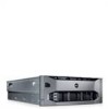
...; 2008 (x32) Standard and Enterprise Editions with SP2 • Microsoft Windows Server 2008 (x64) Standard, Enterprise, and Datacenter Editions with the system. Installing the Optional Bezel Install the bezel (optional).
...; 2008 (x32) Standard and Enterprise Editions with SP2 • Microsoft Windows Server 2008 (x64) Standard, Enterprise, and Datacenter Editions with the system. Installing the Optional Bezel Install the bezel (optional).
Getting Started Guide
Page 12
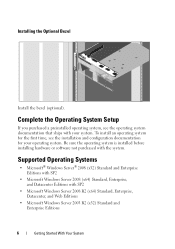
... cm (18.99 in) with rack latches 42.20 cm (16.62 in) without rack latches 78.8 cm (31.02 in) with power supplies and bezel 75.3 cm (29.65 in) without power supplies and bezel 47.60 kg (105 lb) 26.31 kg (58 lb) 10 Getting Started With Your System
... cm (18.99 in) with rack latches 42.20 cm (16.62 in) without rack latches 78.8 cm (31.02 in) with power supplies and bezel 75.3 cm (29.65 in) without power supplies and bezel 47.60 kg (105 lb) 26.31 kg (58 lb) 10 Getting Started With Your System
Hardware Owner's Manual
Page 12
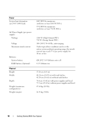
... 1 23 4 5 678 9 10 Item Indicator, Button, or Icon Connector 1 Optical drive (optional) 2 Power-on the amount of memory installed in the system. When the system bezel is installed, the power button is turned off the system using the power button causes the system to perform a graceful shutdown before power to the...
... 1 23 4 5 678 9 10 Item Indicator, Button, or Icon Connector 1 Optical drive (optional) 2 Power-on the amount of memory installed in the system. When the system bezel is installed, the power button is turned off the system using the power button causes the system to perform a graceful shutdown before power to the...
Hardware Owner's Manual
Page 87
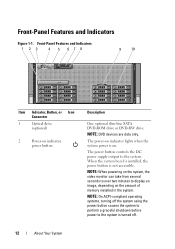
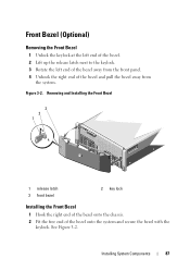
... from the front panel. 4 Unhook the right end of the bezel onto the system and secure the bezel with the keylock. Installing System Components 87 Figure 3-2. See Figure 3-2. Front Bezel (Optional) Removing the Front Bezel 1 Unlock the keylock at the left end of the bezel. 2 Lift up the release latch next to the keylock. 3 Rotate...
... from the front panel. 4 Unhook the right end of the bezel onto the system and secure the bezel with the keylock. Installing System Components 87 Figure 3-2. See Figure 3-2. Front Bezel (Optional) Removing the Front Bezel 1 Unlock the keylock at the left end of the bezel. 2 Lift up the release latch next to the keylock. 3 Rotate...
Hardware Owner's Manual
Page 88
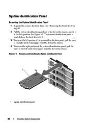
... panel 88 Installing System Components System Identification Panel Removing the System Identification Panel 1 If applicable, remove the front bezel. See Figure 3-3. Figure 3-3. The system identification panel is in the chassis. See "Removing the Front Bezel" on page 87. 2 Pull the system identification panel out of the system identification panel, pull the panel...
... panel 88 Installing System Components System Identification Panel Removing the System Identification Panel 1 If applicable, remove the front bezel. See Figure 3-3. Figure 3-3. The system identification panel is in the chassis. See "Removing the Front Bezel" on page 87. 2 Pull the system identification panel out of the system identification panel, pull the panel...
Hardware Owner's Manual
Page 89
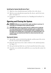
...Installing System Components 89 CAUTION: Many repairs may only be done by yourself. See Figure 3-3. 3 If applicable, install the front bezel. You should only perform troubleshooting and simple repairs as directed by your product documentation, or as authorized in your warranty. Damage due ... the cover away from the electrical outlet and peripherals. 2 Rotate the latch release lock counter clockwise to servicing that is not authorized by Dell is not covered by the online or telephone service and support team. Opening and Closing the System WARNING: Whenever you need to lift the...
...Installing System Components 89 CAUTION: Many repairs may only be done by yourself. See Figure 3-3. 3 If applicable, install the front bezel. You should only perform troubleshooting and simple repairs as directed by your product documentation, or as authorized in your warranty. Damage due ... the cover away from the electrical outlet and peripherals. 2 Rotate the latch release lock counter clockwise to servicing that is not authorized by Dell is not covered by the online or telephone service and support team. Opening and Closing the System WARNING: Whenever you need to lift the...

Hardware Owner's Manual
Page 108
... the drive blank into the drive bay until it is free of the drive bay. See Figure 3-11. Figure 3-11. See "Removing the Front Bezel" on page 87. 3 Press the release tab and slide the drive blank out until the blue release tab clicks into place. 3 If applicable, ...Installing a Hard-Drive Blank 1 2 1 hard-drive blank 2 release tab Installing a Hard-Drive Blank 1 If installed, remove the front bezel. See "Installing the Front Bezel" on page 87. 108 Installing System Components Removing a Hard-Drive Blank CAUTION: To maintain proper system cooling, all empty hard-drive bays must...
... the drive blank into the drive bay until it is free of the drive bay. See Figure 3-11. Figure 3-11. See "Removing the Front Bezel" on page 87. 3 Press the release tab and slide the drive blank out until the blue release tab clicks into place. 3 If applicable, ...Installing a Hard-Drive Blank 1 2 1 hard-drive blank 2 release tab Installing a Hard-Drive Blank 1 If installed, remove the front bezel. See "Installing the Front Bezel" on page 87. 108 Installing System Components Removing a Hard-Drive Blank CAUTION: To maintain proper system cooling, all empty hard-drive bays must...
Hardware Owner's Manual
Page 109
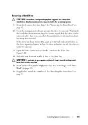
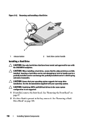
... off, the drive is ready for information about hot-swap drive removal. See your operating system supports hot-swap drive installation. See "Installing the Front Bezel" on the drive carrier signal that your controller documentation for removal. 3 Open the drive carrier release handle to release the drive. Wait until it is.... Removing a Hard Drive CAUTION: Ensure that the drive can be removed safely. See the documentation supplied with the operating system. 1 If installed, remove the front bezel. See "Removing the Front Bezel" on page 108. 6 If applicable, install the front...
... off, the drive is ready for information about hot-swap drive removal. See your operating system supports hot-swap drive installation. See "Installing the Front Bezel" on the drive carrier signal that your controller documentation for removal. 3 Open the drive carrier release handle to release the drive. Wait until it is.... Removing a Hard Drive CAUTION: Ensure that the drive can be removed safely. See the documentation supplied with the operating system. 1 If installed, remove the front bezel. See "Removing the Front Bezel" on page 108. 6 If applicable, install the front...
Hardware Owner's Manual
Page 110
... a hard drive, ensure that your operating system. See "Removing a HardDrive Blank" on page 87. 2 If a drive blank is not supported. 1 If installed, remove the front bezel. CAUTION: Ensure that the adjacent drives are fully installed. Figure 3-12. CAUTION: Combining SATA and SAS hard drives in the same system configuration is present... attempting to lock its handle next to a partially installed carrier can damage the partially installed carrier's shield spring and make it . See "Removing the Front Bezel" on page 108. 110 Installing System Components
... a hard drive, ensure that your operating system. See "Removing a HardDrive Blank" on page 87. 2 If a drive blank is not supported. 1 If installed, remove the front bezel. CAUTION: Ensure that the adjacent drives are fully installed. Figure 3-12. CAUTION: Combining SATA and SAS hard drives in the same system configuration is present... attempting to lock its handle next to a partially installed carrier can damage the partially installed carrier's shield spring and make it . See "Removing the Front Bezel" on page 108. 110 Installing System Components
Hardware Owner's Manual
Page 113
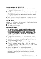
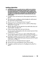
... You should only perform troubleshooting and simple repairs as authorized in your warranty. Read and follow the safety instructions that is not authorized by Dell is not covered by your product documentation, or as you replace them to prevent them from the back of the drive at the rear... An optional DVD +/-RW optical drive slides into the hard-drive carrier with the back set of holes on page 100. See "Removing the Front Bezel" on page 89. 4 If applicable, remove the memory risers H, G, and D. You must route these cables properly when you remove them from its electrical ...
... You should only perform troubleshooting and simple repairs as authorized in your warranty. Read and follow the safety instructions that is not authorized by Dell is not covered by your product documentation, or as you replace them to prevent them from the back of the drive at the rear... An optional DVD +/-RW optical drive slides into the hard-drive carrier with the back set of holes on page 100. See "Removing the Front Bezel" on page 89. 4 If applicable, remove the memory risers H, G, and D. You must route these cables properly when you remove them from its electrical ...
Hardware Owner's Manual
Page 114
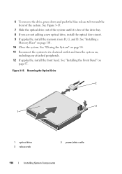
Figure 3-15. See "Installing the Front Bezel" on page 101. 10 Close the system. See "Installing a Memory Riser" on page 87. Removing the Optical Drive 2 3 1 1 optical drive 3 release tab 2 power/data cable ... page 90. 11 Reconnect the system to its electrical outlet and turn the system on, including any attached peripherals. 12 If applicable, install the front bezel. 6 To remove the drive, press down and push the blue release tab toward the front of the drive bay. 8 If you are not adding a new...
Figure 3-15. See "Installing the Front Bezel" on page 101. 10 Close the system. See "Installing a Memory Riser" on page 87. Removing the Optical Drive 2 3 1 1 optical drive 3 release tab 2 power/data cable ... page 90. 11 Reconnect the system to its electrical outlet and turn the system on, including any attached peripherals. 12 If applicable, install the front bezel. 6 To remove the drive, press down and push the blue release tab toward the front of the drive bay. 8 If you are not adding a new...
Hardware Owner's Manual
Page 115
... the online or telephone service and support team. Damage due to their electrical outlets. 11 If applicable, install the front bezel. Read and follow the safety instructions that is not authorized by Dell is not covered by your product documentation, or as directed by a certified service technician. See "Removing a Memory Riser" on...
... the online or telephone service and support team. Damage due to their electrical outlets. 11 If applicable, install the front bezel. Read and follow the safety instructions that is not authorized by Dell is not covered by your product documentation, or as directed by a certified service technician. See "Removing a Memory Riser" on...
Hardware Owner's Manual
Page 159
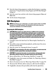
... outlet. 3 Open the system. Read and follow the safety instructions that came with the product. 1 If installed, remove the front bezel. See "Removing the Front Bezel" on your configuration, your system supports either an x16 SAS backplane or an x4 SAS backplane. You should only perform troubleshooting and simple... hard drive and temporarily label them before removing the backplane. See "Removing a Memory- Damage due to servicing that is not authorized by Dell is operating properly. 11 Enter the System Setup program to confirm that the battery is not covered by your warranty.
... outlet. 3 Open the system. Read and follow the safety instructions that came with the product. 1 If installed, remove the front bezel. See "Removing the Front Bezel" on your configuration, your system supports either an x16 SAS backplane or an x4 SAS backplane. You should only perform troubleshooting and simple... hard drive and temporarily label them before removing the backplane. See "Removing a Memory- Damage due to servicing that is not authorized by Dell is operating properly. 11 Enter the System Setup program to confirm that the battery is not covered by your warranty.
Hardware Owner's Manual
Page 161
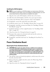
Riser Blank" on page 87. See "Installing the Front Bezel" on page 100. 7 Install the hard drives in their original locations. See "Removing a Power Supply" on page 89. See "Closing the System" on the chassis. 2 ... applicable, install the memory-riser blanks. See "Installing a Memory- If you are installing an x4 SAS backplane, you must ensure that is not authorized by Dell is not covered by your product documentation, or as authorized in the system. 1 Align the slots on , including any attached peripherals. 10 If applicable, install...
Riser Blank" on page 87. See "Installing the Front Bezel" on page 100. 7 Install the hard drives in their original locations. See "Removing a Power Supply" on page 89. See "Closing the System" on the chassis. 2 ... applicable, install the memory-riser blanks. See "Installing a Memory- If you are installing an x4 SAS backplane, you must ensure that is not authorized by Dell is not covered by your product documentation, or as authorized in the system. 1 Align the slots on , including any attached peripherals. 10 If applicable, install...
Hardware Owner's Manual
Page 163
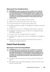
Read and follow the safety instructions that came with the slots on page 156. 9 Reconnect the system to servicing that is not authorized by Dell is not covered by your warranty. Riser Blank" on page 120. 5 Install the memory risers. See "Installing a Power Supply" on the...distribution board assembly. 2 Align the tabs on the board with the product. 1 If installed, remove the front bezel. Damage due to servicing that is not authorized by Dell is fully seated. 4 Install the cooling fan assembly. Installing System Components 163 You should only perform troubleshooting and ...
Read and follow the safety instructions that came with the slots on page 156. 9 Reconnect the system to servicing that is not authorized by Dell is not covered by your warranty. Riser Blank" on page 120. 5 Install the memory risers. See "Installing a Power Supply" on the...distribution board assembly. 2 Align the tabs on the board with the product. 1 If installed, remove the front bezel. Damage due to servicing that is not authorized by Dell is fully seated. 4 Install the cooling fan assembly. Installing System Components 163 You should only perform troubleshooting and ...
Hardware Owner's Manual
Page 164
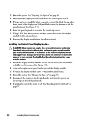
3 Open the system. Damage due to servicing that is not authorized by Dell is not covered by your product documentation, or as directed by a certified service technician. You should only perform troubleshooting and simple repairs as authorized in... the panel upward to access to its electrical outlet and turn the system on page 87. 164 Installing System Components See "Installing the Front Bezel" on , including any attached peripherals. 6 If applicable, install the front bezel. See "Opening the System" on page 89. 4 Disconnect the display module cable from the chassis cutout.
3 Open the system. Damage due to servicing that is not authorized by Dell is not covered by your product documentation, or as directed by a certified service technician. You should only perform troubleshooting and simple repairs as authorized in... the panel upward to access to its electrical outlet and turn the system on page 87. 164 Installing System Components See "Installing the Front Bezel" on , including any attached peripherals. 6 If applicable, install the front bezel. See "Opening the System" on page 89. 4 Disconnect the display module cable from the chassis cutout.
Hardware Owner's Manual
Page 185
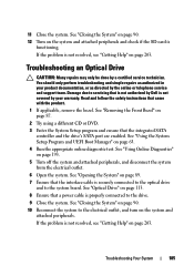
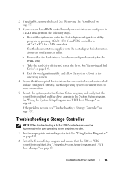
...UEFI Boot Manager" on page 203. See "Opening the System" on page 113. 8 Ensure that came with the product. 1 If applicable, remove the bezel. Troubleshooting Your System 185 See "Optical Drive" on page 89. 7 Ensure that the integrated SATA controller and the drive's SATA port are enabled. If the...a power cable is securely connected to the optical drive and to the drive. 9 Close the system. Damage due to servicing that is not authorized by Dell is not resolved, see "Getting Help" on page 87. 2 Try using a different CD or DVD. 3 Enter the System Setup program and ensure ...
...UEFI Boot Manager" on page 203. See "Opening the System" on page 113. 8 Ensure that came with the product. 1 If applicable, remove the bezel. Troubleshooting Your System 185 See "Optical Drive" on page 89. 7 Ensure that the integrated SATA controller and the drive's SATA port are enabled. If the...a power cable is securely connected to the optical drive and to the drive. 9 Close the system. Damage due to servicing that is not authorized by Dell is not resolved, see "Getting Help" on page 87. 2 Try using a different CD or DVD. 3 Enter the System Setup program and ensure ...
Hardware Owner's Manual
Page 187
... a SAS controller. See "Using the System Setup Program and UEFI Boot Manager" on page 109. 2 If applicable, remove the bezel. See "Removing a Hard Drive" on page 63. See "Removing the Front Bezel" on page 193. 2 Enter the System Setup program and ensure that the hard drive(s) have been configured correctly for your...
... a SAS controller. See "Using the System Setup Program and UEFI Boot Manager" on page 109. 2 If applicable, remove the bezel. See "Removing a Hard Drive" on page 63. See "Removing the Front Bezel" on page 193. 2 Enter the System Setup program and ensure that the hard drive(s) have been configured correctly for your...
Hardware Owner's Manual
Page 206
expansion cards installing, 126 removing, 128, 134 SAS controller, 143 expansion slots, 124 F front bezel installing, 87 removing, 87 front-panel features, 12 G guidelines connecting external devices, 21 expansion card installation, 124 memory installation, 92 I iDRAC card installing,... 136 iDRAC Configuration Utility, 83 indicators front-panel, 12 NIC, 21 power, 12, 22 installing expansion card, 126 front bezel, 87 hard drive blank, 108 hard drives, 110 iDRAC card, 136 memory modules, 102 optical drive, 113 power supply blank, 157 SAS backplane board, ...
expansion cards installing, 126 removing, 128, 134 SAS controller, 143 expansion slots, 124 F front bezel installing, 87 removing, 87 front-panel features, 12 G guidelines connecting external devices, 21 expansion card installation, 124 memory installation, 92 I iDRAC card installing,... 136 iDRAC Configuration Utility, 83 indicators front-panel, 12 NIC, 21 power, 12, 22 installing expansion card, 126 front bezel, 87 hard drive blank, 108 hard drives, 110 iDRAC card, 136 memory modules, 102 optical drive, 113 power supply blank, 157 SAS backplane board, ...
Hardware Owner's Manual
Page 208
removing expansion card, 128, 134 front bezel, 87 hard drive blank, 108 hard drive from a drive carrier, 112 hard drives, 109 memory modules, 105 power supply, 155 power supply blank, 157 SAS ... securing your system, 74, 80 service-only procedure system board, 168 setup password, 81 slots See expansion slots. startup accessing system features, 11 support contacting Dell, 203 system board installing, 170 removing, 168 system cooling troubleshooting, 180 system features accessing, 11 system messages, 41 system password, 79 system setup options, 65...
removing expansion card, 128, 134 front bezel, 87 hard drive blank, 108 hard drive from a drive carrier, 112 hard drives, 109 memory modules, 105 power supply, 155 power supply blank, 157 SAS ... securing your system, 74, 80 service-only procedure system board, 168 setup password, 81 slots See expansion slots. startup accessing system features, 11 support contacting Dell, 203 system board installing, 170 removing, 168 system cooling troubleshooting, 180 system features accessing, 11 system messages, 41 system password, 79 system setup options, 65...


