Information Update
Page 3
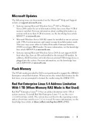
...issue may occur either in Unified Extensible Firmware Interface (UEFI) or in the internal SD module. To install Red Hat Enterprise Linux 5.4, use the virtual flash feature... KB980598 at kbase.redhat.com/faq/docs/DOC-25412. In addition, iSCSI boot does not work when an external USB storage device is used. When you are documented on systems with 1 TB of memory, see the knowledge base ... on systems with 1 TB of memory installed. Flash Memory The VFlash media provided by Dell is Not Used) Red Hat® Enterprise Linux® 5.4 has an address limitation with more than 4 GB ...
...issue may occur either in Unified Extensible Firmware Interface (UEFI) or in the internal SD module. To install Red Hat Enterprise Linux 5.4, use the virtual flash feature... KB980598 at kbase.redhat.com/faq/docs/DOC-25412. In addition, iSCSI boot does not work when an external USB storage device is used. When you are documented on systems with 1 TB of memory, see the knowledge base ... on systems with 1 TB of memory installed. Flash Memory The VFlash media provided by Dell is Not Used) Red Hat® Enterprise Linux® 5.4 has an address limitation with more than 4 GB ...
Getting Started Guide
Page 11
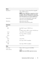
SAS and SATA hard disks on the x4 backplane. x16 backplanes do not support SATA drives. Optional internal SATA DVD or DVD+RW Optional external USB DVD-ROM Optional internal USB Optional internal dual SD module Four RJ-45 using a 1 GbE I/O riser Or Two RJ-45 and two SPF+ using a 10 Gb I/O .... Getting Started With Your System 9 Drives Hard drives Optical drive Flash drive Connectors Back NIC Serial USB Video Front Video USB Internal USB Video Video type Video memory Up to sixteen 2.5-inch, internal hot-swappable SAS or SSD hard drives NOTE: Only one SATA drive is supported on the same...
SAS and SATA hard disks on the x4 backplane. x16 backplanes do not support SATA drives. Optional internal SATA DVD or DVD+RW Optional external USB DVD-ROM Optional internal USB Optional internal dual SD module Four RJ-45 using a 1 GbE I/O riser Or Two RJ-45 and two SPF+ using a 10 Gb I/O .... Getting Started With Your System 9 Drives Hard drives Optical drive Flash drive Connectors Back NIC Serial USB Video Front Video USB Internal USB Video Video type Video memory Up to sixteen 2.5-inch, internal hot-swappable SAS or SSD hard drives NOTE: Only one SATA drive is supported on the same...
Hardware Owner's Manual
Page 6
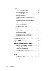
... Drive 115 Cooling Fans 116 Removing a Cooling Fan 116 Installing a Cooling Fan 117 Removing the Cooling Fan Assembly 118 Installing the Cooling Fan Assembly 120 Internal USB Memory Key 120 Integrated NIC Hardware Key 123 Expansion Cards and Expansion-Card Riser . . . . . 124 Expansion Card Installation Guidelines. . . . . . 124 Installing an Expansion Card 126...
... Drive 115 Cooling Fans 116 Removing a Cooling Fan 116 Installing a Cooling Fan 117 Removing the Cooling Fan Assembly 118 Installing the Cooling Fan Assembly 120 Internal USB Memory Key 120 Integrated NIC Hardware Key 123 Expansion Cards and Expansion-Card Riser . . . . . 124 Expansion Card Installation Guidelines. . . . . . 124 Installing an Expansion Card 126...
Hardware Owner's Manual
Page 9
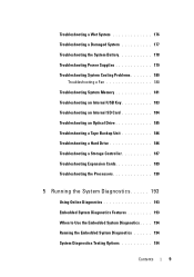
... Troubleshooting the System Battery 178 Troubleshooting Power Supplies 179 Troubleshooting System Cooling Problems 180 Troubleshooting a Fan 180 Troubleshooting System Memory 181 Troubleshooting an Internal USB Key 183 Troubleshooting an Internal SD Card 184 Troubleshooting an Optical Drive 185 Troubleshooting a Tape Backup Unit 186 Troubleshooting a Hard Drive 186 Troubleshooting a Storage Controller 187 Troubleshooting Expansion...
... Troubleshooting the System Battery 178 Troubleshooting Power Supplies 179 Troubleshooting System Cooling Problems 180 Troubleshooting a Fan 180 Troubleshooting System Memory 181 Troubleshooting an Internal USB Key 183 Troubleshooting an Internal SD Card 184 Troubleshooting an Optical Drive 185 Troubleshooting a Tape Backup Unit 186 Troubleshooting a Hard Drive 186 Troubleshooting a Storage Controller 187 Troubleshooting Expansion...
Hardware Owner's Manual
Page 53
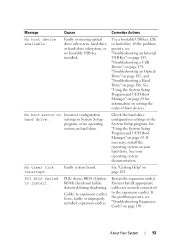
...install. No boot sector on page 63. Check the hard-drive configuration settings in System Setup program, or no bootable USB key installed. faulty or improperly installed expansion card(s). About Your System 53 Message Causes Corrective Actions No boot device available...the problem persists, see "Troubleshooting Expansion Cards" on your operating system documentation. If the problem persists, see "Troubleshooting an Internal USB Key" on page 183, "Troubleshooting a USB Device" on page 174, "Troubleshooting an Optical Drive" on page 185, and "Troubleshooting a Hard Drive" on page...
...install. No boot sector on page 63. Check the hard-drive configuration settings in System Setup program, or no bootable USB key installed. faulty or improperly installed expansion card(s). About Your System 53 Message Causes Corrective Actions No boot device available...the problem persists, see "Troubleshooting Expansion Cards" on your operating system documentation. If the problem persists, see "Troubleshooting an Internal USB Key" on page 183, "Troubleshooting a USB Device" on page 174, "Troubleshooting an Optical Drive" on page 185, and "Troubleshooting a Hard Drive" on page...
Hardware Owner's Manual
Page 59
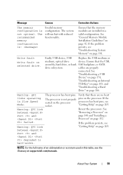
...system will run but with reduced functionality. If the problem persists, see socket. Write fault Write fault on page 181. Faulty USB device, USB Replace the USB medium or medium, optical drive device. SAS backplane, or SATA drive subsystem. See between "Removing a Processor" on page 186....not properly pins on page 203. Ensure that the memory modules are installed in Slow Speed Mode. See "Troubleshooting a USB Device" on page 174, "Troubleshooting an Internal USB Key" on page 183, and "Troubleshooting a Hard Drive" on Port and page 148 and "Installing a Verify that...
...system will run but with reduced functionality. If the problem persists, see socket. Write fault Write fault on page 181. Faulty USB device, USB Replace the USB medium or medium, optical drive device. SAS backplane, or SATA drive subsystem. See between "Removing a Processor" on page 186....not properly pins on page 203. Ensure that the memory modules are installed in Slow Speed Mode. See "Troubleshooting a USB Device" on page 174, "Troubleshooting an Internal USB Key" on page 183, and "Troubleshooting a Hard Drive" on Port and page 148 and "Installing a Verify that...
Hardware Owner's Manual
Page 70
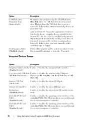
...must manually set the emulation type to act as a hard drive. Auto automatically chooses an emulation type. Internal USB Port (On default) Enables or disables the internal USB port. The NICs can also be accessed through the system's management controller. 70 Using the System Setup ...appropriate emulation type for the device, except for a USB flash drive. Option USB Flash Drive Emulation Type (Auto default) Boot Sequence Retry (Disabled default) Description Determines the emulation type for devices installed in the internal SD card slot will reattempt to boot after 30 seconds...
...must manually set the emulation type to act as a hard drive. Auto automatically chooses an emulation type. Internal USB Port (On default) Enables or disables the internal USB port. The NICs can also be accessed through the system's management controller. 70 Using the System Setup ...appropriate emulation type for the device, except for a USB flash drive. Option USB Flash Drive Emulation Type (Auto default) Boot Sequence Retry (Disabled default) Description Determines the emulation type for devices installed in the internal SD card slot will reattempt to boot after 30 seconds...
Hardware Owner's Manual
Page 120
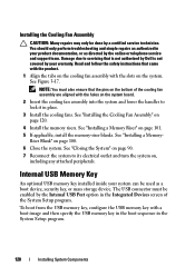
...the system board. 2 Insert the cooling fan assembly into the system and lower the handles to servicing that is not authorized by Dell is not covered by the Internal USB Port option in place. 3 Install the cooling fans. See "Installing a MemoryRiser Blank" on page 120. 4 Install the ...memory risers. See "Installing the Cooling Fan Assembly" on page 100. 6 Close the system. Internal USB Memory Key An optional USB memory key installed inside your product documentation, or as a boot device, security key, or mass storage device. Damage due to lock it...
...the system board. 2 Insert the cooling fan assembly into the system and lower the handles to servicing that is not authorized by Dell is not covered by the Internal USB Port option in place. 3 Install the cooling fans. See "Installing a MemoryRiser Blank" on page 120. 4 Install the ...memory risers. See "Installing the Cooling Fan Assembly" on page 100. 6 Close the system. Internal USB Memory Key An optional USB memory key installed inside your product documentation, or as a boot device, security key, or mass storage device. Damage due to lock it...

Hardware Owner's Manual
Page 168
... repairs may be done by the online or telephone service and support team. Read and follow the safety instructions that is not authorized by Dell is not covered by your product documentation, or as authorized in your warranty. See "Opening the System" on page 123. 10 Remove ... create a recovery key during program or system setup. See "Removing the Cooling Fan Assembly" on page 99. 4 Remove the memory risers. See "Internal USB Memory Key" on page 161. 168 Installing System Components See "Removing the Power Distribution Board" on page 120. 9 If applicable, remove the NIC hardware...
... repairs may be done by the online or telephone service and support team. Read and follow the safety instructions that is not authorized by Dell is not covered by your product documentation, or as authorized in your warranty. See "Opening the System" on page 123. 10 Remove ... create a recovery key during program or system setup. See "Removing the Cooling Fan Assembly" on page 99. 4 Remove the memory risers. See "Internal USB Memory Key" on page 161. 168 Installing System Components See "Removing the Power Distribution Board" on page 120. 9 If applicable, remove the NIC hardware...

Hardware Owner's Manual
Page 170
...Dell is not covered by the online or telephone service and support team. See "Removing a Processor" on page 148 and "Installing a Processor" on page 152. 10 If applicable, install the NIC hardware key on the system board. See "Integrated NIC Hardware Key" on page 123. 11 If applicable, install the internal USB...on page 135, and "Installing the Integrated Storage Controller Card" on page 145. 13 Install the cooling fan assembly. See "Internal USB Memory Key" on page 120. 170 Installing System Components Read and follow the safety instructions that came with the product. 1 ...
...Dell is not covered by the online or telephone service and support team. See "Removing a Processor" on page 148 and "Installing a Processor" on page 152. 10 If applicable, install the NIC hardware key on the system board. See "Integrated NIC Hardware Key" on page 123. 11 If applicable, install the internal USB...on page 135, and "Installing the Integrated Storage Controller Card" on page 145. 13 Install the cooling fan assembly. See "Internal USB Memory Key" on page 120. 170 Installing System Components Read and follow the safety instructions that came with the product. 1 ...
Hardware Owner's Manual
Page 183
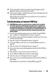
... on page 70. 2 Turn off the system and attached peripherals, and disconnect the system from the electrical outlet. 3 Open the system. Troubleshooting an Internal USB Key CAUTION: Many repairs may only be done by the online or telephone service and support team. See "Closing the System" on page 90. 6...it. Read and follow the safety instructions that came with the product. 1 Enter the System Setup program and ensure that the internal USB key port is not covered by Dell is enabled. If the problem persists after all memory modules have been checked, see "Getting Help" on the system and ...
... on page 70. 2 Turn off the system and attached peripherals, and disconnect the system from the electrical outlet. 3 Open the system. Troubleshooting an Internal USB Key CAUTION: Many repairs may only be done by the online or telephone service and support team. See "Closing the System" on page 90. 6...it. Read and follow the safety instructions that came with the product. 1 Enter the System Setup program and ensure that the internal USB key port is not covered by Dell is enabled. If the problem persists after all memory modules have been checked, see "Getting Help" on the system and ...

Hardware Owner's Manual
Page 199
... Description Control panel interface connector Control panel USB interface connector SATA A connector Processor 4 Processor 2 System cooling fan 1 Power distribution board connector System cooling fan 4 Internal USB connector PCIE_G2_X4 PCIE_G2_X8 PCIE_G2_X8 PCIE_G2_X8 PCIE_G2_X4 PCIE_G2_X4... Password enable jumper NVRAM clear jumper PCIE_G2_X16 I/O card connector Internal storage controller card connector Power connector System cooling fan 5 ...
... Description Control panel interface connector Control panel USB interface connector SATA A connector Processor 4 Processor 2 System cooling fan 1 Power distribution board connector System cooling fan 4 Internal USB connector PCIE_G2_X4 PCIE_G2_X8 PCIE_G2_X8 PCIE_G2_X8 PCIE_G2_X4 PCIE_G2_X4... Password enable jumper NVRAM clear jumper PCIE_G2_X16 I/O card connector Internal storage controller card connector Power connector System cooling fan 5 ...

Hardware Owner's Manual
Page 209
...74 troubleshooting battery, 178 CD drive, 185 cooling fans, 180 damaged system, 177 expansion card, 189 external connections, 173 hard drive, 186 internal USB key, 183 keyboard, 174 memory, 181 NIC, 175 power supplies, 179 SAS RAID controller daughter card, 187 SD card, 183 system cooling...176 U UEFI Boot Manager entering, 76 main screen, 77 System Utilities screen, 78 UEFI Boot Settings screen, 77 USB front-panel connectors, 12 internal connector for memory key, 120 USB key troubleshooting, 183 V video front-panel connectors, 12 troubleshooting, 174 W warning messages, 60 warranty, 60 wet ...
...74 troubleshooting battery, 178 CD drive, 185 cooling fans, 180 damaged system, 177 expansion card, 189 external connections, 173 hard drive, 186 internal USB key, 183 keyboard, 174 memory, 181 NIC, 175 power supplies, 179 SAS RAID controller daughter card, 187 SD card, 183 system cooling...176 U UEFI Boot Manager entering, 76 main screen, 77 System Utilities screen, 78 UEFI Boot Settings screen, 77 USB front-panel connectors, 12 internal connector for memory key, 120 USB key troubleshooting, 183 V video front-panel connectors, 12 troubleshooting, 174 W warning messages, 60 warranty, 60 wet ...


