
Glossary
Page 2
... power indicator. See device driver. ERA allows you to perform remote, or "out-ofband," server management on the system board. expansion card - DC - Double-data rate. Dual in card, such as NICs. Electromagnetic interference. expansion bus - An expansion card adds some other program to a client system. The part of translating Internet domain names, such as www.example.com, into an expansion-card connector on your network server using a remote access controller. A chip or expansion card that controls the transfer of tests...
... power indicator. See device driver. ERA allows you to perform remote, or "out-ofband," server management on the system board. expansion card - DC - Double-data rate. Dual in card, such as NICs. Electromagnetic interference. expansion bus - An expansion card adds some other program to a client system. The part of translating Internet domain names, such as www.example.com, into an expansion-card connector on your network server using a remote access controller. A chip or expansion card that controls the transfer of tests...

Glossary
Page 3
... to -point bidirectional serial links intended for plugging in an expansion card. Hz - I /O activity can be programmed and reprogrammed using a software utility. InfiniBand - Internet Protocol version 6. 3 flash memory - Gram(s). Integrated Dell Remote Access Controller. File allocation table. g - A video mode that can optionally use a FAT file system structure. A controller that uses the Internet SCSI protocol. A keyboard is an input device, and a monitor is the data path and physical interface between the system board and storage devices. A remote access controller that...
... to -point bidirectional serial links intended for plugging in an expansion card. Hz - I /O activity can be programmed and reprogrammed using a software utility. InfiniBand - Internet Protocol version 6. 3 flash memory - Gram(s). Integrated Dell Remote Access Controller. File allocation table. g - A video mode that can optionally use a FAT file system structure. A controller that uses the Internet SCSI protocol. A keyboard is an input device, and a monitor is the data path and physical interface between the system board and storage devices. A remote access controller that...

Glossary
Page 8
...) DDR3 memory module. A USB connector provides a single connection point for video adapters with greater resolution and color display capabilities than previous standards. VGA and SVGA are connected in the configuration software for the devices. SMP - Disk striping writes data across three or more processors connected via a high-bandwidth link and managed by an operating system, where each processor has equal access to enable or disable the termination on these devices by changing jumper or switch settings on each...
...) DDR3 memory module. A USB connector provides a single connection point for video adapters with greater resolution and color display capabilities than previous standards. VGA and SVGA are connected in the configuration software for the devices. SMP - Disk striping writes data across three or more processors connected via a high-bandwidth link and managed by an operating system, where each processor has equal access to enable or disable the termination on these devices by changing jumper or switch settings on each...
Information Update
Page 3
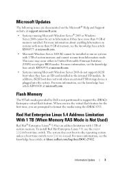
... knowledge base article KB980598 at support.microsoft.com: • Systems running Microsoft Windows Server 2008 do not support iSCSI boot when they have an SD card installed in legacy BIOS modes. To install Red Hat Enterprise Linux 5.4, use the virtual flash feature for the first time, you use the mem= 1024M boot time switch. In addition, iSCSI boot does not work when an external USB storage device is used. For more information, see...
... knowledge base article KB980598 at support.microsoft.com: • Systems running Microsoft Windows Server 2008 do not support iSCSI boot when they have an SD card installed in legacy BIOS modes. To install Red Hat Enterprise Linux 5.4, use the virtual flash feature for the first time, you use the mem= 1024M boot time switch. In addition, iSCSI boot does not work when an external USB storage device is used. For more information, see...
Hardware Owner's Manual
Page 29
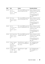
... page 203. Power cycle AC. If the problem persists, see "Getting Help" on page 179. Check power supply. error. See "Troubleshooting Power Supplies" on error. Code Text Causes Corrective Actions E141F CPU # protocol error. The system BIOS reported a Remove AC power to the system for 10 seconds and Power cycle restart the system. system for 10 seconds and restart the system. E1610 Power Supply # (### W) missing. processor bus parity error. E1421 CPU # initializati on...
... page 203. Power cycle AC. If the problem persists, see "Getting Help" on page 179. Check power supply. error. See "Troubleshooting Power Supplies" on error. Code Text Causes Corrective Actions E141F CPU # protocol error. The system BIOS reported a Remove AC power to the system for 10 seconds and Power cycle restart the system. system for 10 seconds and restart the system. E1610 Power Supply # (### W) missing. processor bus parity error. E1421 CPU # initializati on...
Hardware Owner's Manual
Page 38
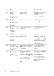
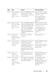
...181. The system BIOS has Remove AC power to the disabled memory single-bit system for specific error messages. Check screen message. Contact support. Reseat DIMM. "##" see "Troubleshooting represents the memory System Memory" on error. Review User Guide. E2022 General failure during POST. Code Text Causes Corrective Actions E2021 Incorrect Incorrect memory memory configuration. ation. See "Troubleshooting System Memory" on ##. General failure after video. E2110 Multibit The memory module in a valid configuration. Check screen for 10 seconds...
...181. The system BIOS has Remove AC power to the disabled memory single-bit system for specific error messages. Check screen message. Contact support. Reseat DIMM. "##" see "Troubleshooting represents the memory System Memory" on error. Review User Guide. E2022 General failure during POST. Code Text Causes Corrective Actions E2021 Incorrect Incorrect memory memory configuration. ation. See "Troubleshooting System Memory" on ##. General failure after video. E2110 Multibit The memory module in a valid configuration. Check screen for 10 seconds...
Hardware Owner's Manual
Page 39
... many errors. "## & ##" represents the memory module pair implicated by the BIOS. System cover has been removed. Check the SEL for 10 seconds and restart the system. The SEL is unable to log any more information and then clear the SEL. If the problem persists, see "Troubleshooting System Memory" on page 203. The eleventh message instructs the user to check the SEL for 10 seconds and DIMM ##. Review & clear log. determined the memory...
... many errors. "## & ##" represents the memory module pair implicated by the BIOS. System cover has been removed. Check the SEL for 10 seconds and restart the system. The SEL is unable to log any more information and then clear the SEL. If the problem persists, see "Troubleshooting System Memory" on page 203. The eleventh message instructs the user to check the SEL for 10 seconds and DIMM ##. Review & clear log. determined the memory...
Hardware Owner's Manual
Page 45
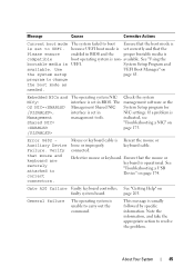
... "Troubleshooting a USB Device" on Error 8602 Auxiliary Device Failure. because UEFI boot mode is non- System Setup Program and available. Note the information, and take the appropriate action to change the boot mode as needed. About Your System 45 Ensure that the Please ensure enabled in BIOS and the proper bootable media is compatible boot operating system is set to UEFI. See "Getting Help" on the system setup page 63. Use UEFI Boot Manager...
... "Troubleshooting a USB Device" on Error 8602 Auxiliary Device Failure. because UEFI boot mode is non- System Setup Program and available. Note the information, and take the appropriate action to change the boot mode as needed. About Your System 45 Ensure that the Please ensure enabled in BIOS and the proper bootable media is compatible boot operating system is set to UEFI. See "Getting Help" on the system setup page 63. Use UEFI Boot Manager...
Hardware Owner's Manual
Page 53
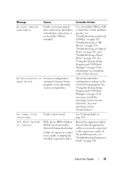
...your hard drive. PCIe device BIOS (Option ROM) checksum failure detected during shadowing. Reseat the expansion card(s). See "Using the System Setup Program and UEFI Boot Manager" on Incorrect configuration hard drive. PCI BIOS failed to the expansion card(s). Message Causes Corrective Actions No boot device available. No boot sector on page 63. If necessary, install the operating system on page 203. See "Getting Help" on your operating system documentation. If the problem persists, see "Troubleshooting an Internal USB Key" on page 183, "Troubleshooting a USB Device" on...
...your hard drive. PCIe device BIOS (Option ROM) checksum failure detected during shadowing. Reseat the expansion card(s). See "Using the System Setup Program and UEFI Boot Manager" on Incorrect configuration hard drive. PCI BIOS failed to the expansion card(s). Message Causes Corrective Actions No boot device available. No boot sector on page 63. If necessary, install the operating system on page 203. See "Getting Help" on your operating system documentation. If the problem persists, see "Troubleshooting an Internal USB Key" on page 183, "Troubleshooting a USB Device" on...
Hardware Owner's Manual
Page 63
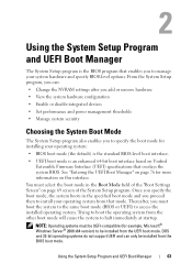
... operating system from the BIOS boot mode. DOS and 32-bit operating systems do not support UEFI and can : • Change the NVRAM settings after you add or remove hardware • View the system hardware configuration • Enable or disable integrated devices • Set performance and power management thresholds • Manage system security Choosing the System Boot Mode The System Setup program also enables you to specify the boot mode for installing your operating system: • BIOS boot mode (the default) is the standard BIOS-level boot interface. • UEFI boot mode...
... operating system from the BIOS boot mode. DOS and 32-bit operating systems do not support UEFI and can : • Change the NVRAM settings after you add or remove hardware • View the system hardware configuration • Enable or disable integrated devices • Set performance and power management thresholds • Manage system security Choosing the System Boot Mode The System Setup program also enables you to specify the boot mode for installing your operating system: • BIOS boot mode (the default) is the standard BIOS-level boot interface. • UEFI boot mode...
Hardware Owner's Manual
Page 69
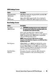
... access the UEFI boot manager utility by rebooting the system and pressing when prompted to BIOS allows compatibility with non-UEFI operating systems. NOTE: Setting this field tells the system where the operating system files needed for the device. Using the System Setup Program and UEFI Boot Manager 69 If Boot Mode is set this option to UEFI disables the Boot Sequence, Hard-Disk Drive Sequence, and USB Flash Drive Emulation Type fields. SATA Settings Screen Option Embedded SATA (Off default) Port A (Off default) Description ATA Mode enables...
... access the UEFI boot manager utility by rebooting the system and pressing when prompted to BIOS allows compatibility with non-UEFI operating systems. NOTE: Setting this field tells the system where the operating system files needed for the device. Using the System Setup Program and UEFI Boot Manager 69 If Boot Mode is set this option to UEFI disables the Boot Sequence, Hard-Disk Drive Sequence, and USB Flash Drive Emulation Type fields. SATA Settings Screen Option Embedded SATA (Off default) Port A (Off default) Description ATA Mode enables...
Hardware Owner's Manual
Page 70
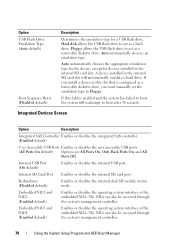
.... 70 Using the System Setup Program and UEFI Boot Manager Option USB Flash Drive Emulation Type (Auto default) Boot Sequence Retry (Disabled default) Description Determines the emulation type for devices installed in the internal SD card slot. Embedded NIC3 and NIC4 (Enabled default) Enables or disables the operating system interface of the embedded NICs. If you install a device in this field is configured as a removable diskette drive. Redundancy (Disabled default) Enables or disables the internal dual SD module mirror mode. Hard disk allows the USB flash drive to act...
.... 70 Using the System Setup Program and UEFI Boot Manager Option USB Flash Drive Emulation Type (Auto default) Boot Sequence Retry (Disabled default) Description Determines the emulation type for devices installed in the internal SD card slot. Embedded NIC3 and NIC4 (Enabled default) Enables or disables the operating system interface of the embedded NICs. If you install a device in this field is configured as a removable diskette drive. Redundancy (Disabled default) Enables or disables the internal dual SD module mirror mode. Hard disk allows the USB flash drive to act...
Hardware Owner's Manual
Page 71
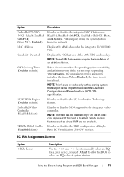
... DMA Engine (Disabled default) Embedded Video Controller (Enabled default) SR-IOV Global Enable (Enabled default) Description Enables or disables the integrated NIC. Enables or disables BIOS support for the integrated 10/100/1000 NIC. PCI IRQ Assignments Screen Option Description Use the and keys to manually select an IRQ for activity, and aids in video card is disabled, remote access features such as virtual KVM are Enabled, Enabled with PXE, Enabled with PXE; Displays the NIC features of the Advanced Configuration and Power Interface (ACPI) 3.0b specification. NOTE...
... DMA Engine (Disabled default) Embedded Video Controller (Enabled default) SR-IOV Global Enable (Enabled default) Description Enables or disables the integrated NIC. Enables or disables BIOS support for the integrated 10/100/1000 NIC. PCI IRQ Assignments Screen Option Description Use the and keys to manually select an IRQ for activity, and aids in video card is disabled, remote access features such as virtual KVM are Enabled, Enabled with PXE, Enabled with PXE; Displays the NIC features of the Advanced Configuration and Power Interface (ACPI) 3.0b specification. NOTE...
Hardware Owner's Manual
Page 82
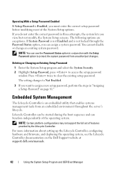
... embedded utility that enables systems management tasks from unauthorized changes. Operating With a Setup Password Enabled If Setup Password is Enabled, you can assign a system password. NOTE: Certain platform configurations may not support the full set of the operating system. For more information about setting up the Lifecycle Controller, configuring hardware and firmware, and deploying the operating system, see the Lifecycle Controller documentation on page 81." Lifecycle Controller can be started during the boot sequence and can use the Password Status...
... embedded utility that enables systems management tasks from unauthorized changes. Operating With a Setup Password Enabled If Setup Password is Enabled, you can assign a system password. NOTE: Certain platform configurations may not support the full set of the operating system. For more information about setting up the Lifecycle Controller, configuring hardware and firmware, and deploying the operating system, see the Lifecycle Controller documentation on page 81." Lifecycle Controller can be started during the boot sequence and can use the Password Status...
Hardware Owner's Manual
Page 128
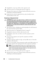
... cables from the card. 4 If applicable, remove the screw that came with the product. 1 Turn off the system, including any cables to its electrical outlet and turn the system on , including any device drivers required for the card. See Figure 3-20. 6 Grasp the expansion card by the online or telephone service and support team. Removing an Expansion Card CAUTION: Many repairs may only be done by your product documentation...
... cables from the card. 4 If applicable, remove the screw that came with the product. 1 Turn off the system, including any cables to its electrical outlet and turn the system on , including any device drivers required for the card. See Figure 3-20. 6 Grasp the expansion card by the online or telephone service and support team. Removing an Expansion Card CAUTION: Many repairs may only be done by your product documentation...
Hardware Owner's Manual
Page 175
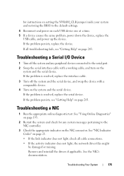
... BIOS to the default settings. 4 Reconnect and power on page 21. • If the link indicator does not light, check all troubleshooting fails, see "Getting Help" on page 203. See "NIC Indicator Codes" on each USB device one at a time. 5 If a device causes the same problem, power down the device, replace the USB cable, and power up the device. for any peripheral devices connected to the serial port. 2 Swap the serial interface cable with a comparable device. 4 Turn on the NIC connector. See the NIC's documentation. Remove...
... BIOS to the default settings. 4 Reconnect and power on page 21. • If the link indicator does not light, check all troubleshooting fails, see "Getting Help" on page 203. See "NIC Indicator Codes" on each USB device one at a time. 5 If a device causes the same problem, power down the device, replace the USB cable, and power up the device. for any peripheral devices connected to the serial port. 2 Swap the serial interface cable with a comparable device. 4 Turn on the NIC connector. See the NIC's documentation. Remove...
Hardware Owner's Manual
Page 176
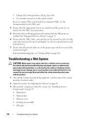
... appropriate drivers are installed and the protocols are using a NIC card instead of the proper type and do not exceed the maximum length. See"Opening the System" on the network are enabled. If you are bound. If all set to servicing that is not authorized by Dell is not covered by your product documentation, or as directed by a certified service technician. Troubleshooting a Wet System CAUTION: Many repairs...
... appropriate drivers are installed and the protocols are using a NIC card instead of the proper type and do not exceed the maximum length. See"Opening the System" on the network are enabled. If you are bound. If all set to servicing that is not authorized by Dell is not covered by your product documentation, or as directed by a certified service technician. Troubleshooting a Wet System CAUTION: Many repairs...
Hardware Owner's Manual
Page 185
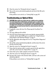
... a power cable is securely connected to the optical drive and to the electrical outlet, and turn on page 63. 4 Run the appropriate online diagnostic test. See "Closing the System" on page 90. 12 Turn on page 87. 2 Try using a different CD or DVD. 3 Enter the System Setup program and ensure that the interface cable is properly connected to servicing that came with the product. 1 If applicable, remove...
... a power cable is securely connected to the optical drive and to the electrical outlet, and turn on page 63. 4 Run the appropriate online diagnostic test. See "Closing the System" on page 90. 12 Turn on page 87. 2 Try using a different CD or DVD. 3 Enter the System Setup program and ensure that the interface cable is properly connected to servicing that came with the product. 1 If applicable, remove...
Hardware Owner's Manual
Page 186
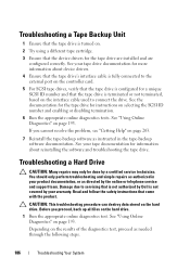
... controller card. 5 For SCSI tape drives, verify that the tape drive is configured for the tape drive are installed and are configured correctly. Before you cannot resolve the problem, see "Getting Help" on the interface cable used to connect the drive. See "Using Online Diagnostics" on the hard drive. 1 Run the appropriate online diagnostics test. You should only perform troubleshooting and simple repairs as authorized in your product documentation, or as instructed in the tape-backup software documentation. Troubleshooting...
... controller card. 5 For SCSI tape drives, verify that the tape drive is configured for the tape drive are installed and are configured correctly. Before you cannot resolve the problem, see "Getting Help" on the interface cable used to connect the drive. See "Using Online Diagnostics" on the hard drive. 1 Run the appropriate online diagnostics test. You should only perform troubleshooting and simple repairs as authorized in your product documentation, or as instructed in the tape-backup software documentation. Troubleshooting...
Hardware Owner's Manual
Page 205
..., 177 Dell contacting, 203 Dell PowerEdge Diagnostics using, 193 diagnostics advanced testing options, 193 testing options, 193 using Dell PowerEdge Diagnostics, 193 DIMMs See memory modules (DIMMs). drive blank installing, 108 removing, 108 drive carrier hard drive, 112 E error messages, 64 expansion card troubleshooting, 189 Index 205 Index B batteries troubleshooting, 178 battery troubleshooting the RAID card battery, 187 battery (system) replacing, 157 blank hard drive, 108 power supply, 157 C cabling optical drive, 113 CD drive troubleshooting, 185 CD/DVD drive See optical drive.
..., 177 Dell contacting, 203 Dell PowerEdge Diagnostics using, 193 diagnostics advanced testing options, 193 testing options, 193 using Dell PowerEdge Diagnostics, 193 DIMMs See memory modules (DIMMs). drive blank installing, 108 removing, 108 drive carrier hard drive, 112 E error messages, 64 expansion card troubleshooting, 189 Index 205 Index B batteries troubleshooting, 178 battery troubleshooting the RAID card battery, 187 battery (system) replacing, 157 blank hard drive, 108 power supply, 157 C cabling optical drive, 113 CD drive troubleshooting, 185 CD/DVD drive See optical drive.


