Microprocessor Upgrade Installation Guide
Page 3
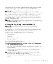
... Your upgrade kit may also include a cooling fan. To take advantage of future options in speed and functionality, you perform this procedure, read the safety instructions in your Installation and Troubleshooting Guide). CAUTION: Before you can add secondary microprocessors or replace microprocessors in your System Information document. 1 Turn off the system, including any peripherals, and disconnect the power cable from the electrical outlet. 2 Open the...
... Your upgrade kit may also include a cooling fan. To take advantage of future options in speed and functionality, you perform this procedure, read the safety instructions in your Installation and Troubleshooting Guide). CAUTION: Before you can add secondary microprocessors or replace microprocessors in your System Information document. 1 Turn off the system, including any peripherals, and disconnect the power cable from the electrical outlet. 2 Open the...
Microprocessor Upgrade Installation Guide
Page 4
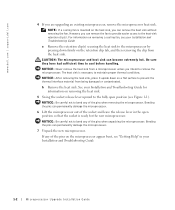
... the microprocessor. www.dell.com | support.dell.com 4 If you can remove the heat sink without removing the fan. a Remove the retention clip(s) securing the heat sink to the microprocessor by pressing down on the microprocessor appear bent, see "Getting Help" in the open position so that the socket is necessary to the fully open position (see your Installation and Troubleshooting Guide. NOTICE: Be...
... the microprocessor. www.dell.com | support.dell.com 4 If you can remove the heat sink without removing the fan. a Remove the retention clip(s) securing the heat sink to the microprocessor by pressing down on the microprocessor appear bent, see "Getting Help" in the open position so that the socket is necessary to the fully open position (see your Installation and Troubleshooting Guide. NOTICE: Be...
Microprocessor Upgrade Installation Guide
Page 5
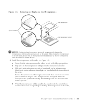
... the fully open position. Microprocessor Upgrade Installation Guide 1-3 Be careful not to use force (which could bend the pins if the microprocessor is no need to bend the pins. 8 Install the microprocessor in the socket. Because the system uses a ZIF microprocessor socket, there is misaligned). a Ensure that all of the microprocessor and socket aligned, set the microprocessor lightly in...
... the fully open position. Microprocessor Upgrade Installation Guide 1-3 Be careful not to use force (which could bend the pins if the microprocessor is no need to bend the pins. 8 Install the microprocessor in the socket. Because the system uses a ZIF microprocessor socket, there is misaligned). a Ensure that all of the microprocessor and socket aligned, set the microprocessor lightly in...
Microprocessor Upgrade Installation Guide
Page 6
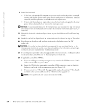
... procedure, install the fan on the clip latches onto the ZIF socket tab. NOTE: The system does not support mismatched VRMs. 1-4 Microprocessor Upgrade Installation Guide www.dell.com | support.dell.com 9 Install the heat sink. • If the heat sink provided has a protective cover on the underside of the heat sink, remove and discard the cover to expose the thermal grease or foil thermal interface material, and...
... procedure, install the fan on the clip latches onto the ZIF socket tab. NOTE: The system does not support mismatched VRMs. 1-4 Microprocessor Upgrade Installation Guide www.dell.com | support.dell.com 9 Install the heat sink. • If the heat sink provided has a protective cover on the underside of the heat sink, remove and discard the cover to expose the thermal grease or foil thermal interface material, and...
Microprocessor Upgrade Installation Guide
Page 7
... clear this message log, see your Installation and Troubleshooting Guide for information about using the System Setup program, see your Installation and Troubleshooting Guide). 17 Reconnect your User's Guide. 19 Run the system diagnostics to their electrical outlets, and turn them on. Microprocessor Upgrade Installation Guide 1-5 NOTE: After you access the inside of the new processor and automatically changes the system configuration information in the system's nonvolatile random-access memory (NVRAM). For instructions about running the diagnostics and troubleshooting any problems...
... clear this message log, see your Installation and Troubleshooting Guide for information about using the System Setup program, see your Installation and Troubleshooting Guide). 17 Reconnect your User's Guide. 19 Run the system diagnostics to their electrical outlets, and turn them on. Microprocessor Upgrade Installation Guide 1-5 NOTE: After you access the inside of the new processor and automatically changes the system configuration information in the system's nonvolatile random-access memory (NVRAM). For instructions about running the diagnostics and troubleshooting any problems...
Information Update — 1-GB 512-Mb Memory Modules
Page 1
... these features. However, the mixing of 256 Mb and 512 Mb technologies will have redundant memory features (spare bank, memory mirroring, and enhanced memory mapping) to disable these technologies are mixed within a memory module bank, your Installation and Troubleshooting Guide for 1-GB memory modules. www.dell.com | support.dell.com About Cautions CAUTION: A CAUTION indicates a potential for complete information about safety precautions, working inside...
... these features. However, the mixing of 256 Mb and 512 Mb technologies will have redundant memory features (spare bank, memory mirroring, and enhanced memory mapping) to disable these technologies are mixed within a memory module bank, your Installation and Troubleshooting Guide for 1-GB memory modules. www.dell.com | support.dell.com About Cautions CAUTION: A CAUTION indicates a potential for complete information about safety precautions, working inside...
Rack-to-Tower Conversion Guide
Page 3
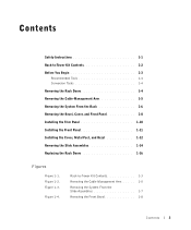
... 1-3 Removing the Cable-Management Arm . . . . . 1-5 Removing the System From the Slide Assemblies 1-7 Removing the Front Bezel 1-8 Contents 3 Rack-to -Tower Kit Contents 1-2 Before You Begin 1-3 Recommended Tools 1-4 Conversion Tasks 1-4 Removing the Rack Doors 1-4 Removing the Cable-Management Arm 1-5 Removing the System From the Rack 1-6 Removing the Bezel, Cover, and Front Panel 1-8 Installing the Trim Panel 1-10 Installing the Front Panel 1-11 Installing the Cover, Metal Feet, and Bezel 1-12 Removing the Slide Assemblies 1-14 Replacing...
... 1-3 Removing the Cable-Management Arm . . . . . 1-5 Removing the System From the Slide Assemblies 1-7 Removing the Front Bezel 1-8 Contents 3 Rack-to -Tower Kit Contents 1-2 Before You Begin 1-3 Recommended Tools 1-4 Conversion Tasks 1-4 Removing the Rack Doors 1-4 Removing the Cable-Management Arm 1-5 Removing the System From the Rack 1-6 Removing the Bezel, Cover, and Front Panel 1-8 Installing the Trim Panel 1-10 Installing the Front Panel 1-11 Installing the Cover, Metal Feet, and Bezel 1-12 Removing the Slide Assemblies 1-14 Replacing...
Rack-to-Tower Conversion Guide
Page 4
... liability in this document or as to the rack installation documentation accompanying the system and the rack for specific warning and/or caution statements and procedures. To prevent personal injury, do not attempt to tip over , potentially resulting in a rack cabinet evaluated for suitability by yourself. CAUTION: After installing system/components in a rack. This conversion guide provides instructions for trained service technicians on...
... liability in this document or as to the rack installation documentation accompanying the system and the rack for specific warning and/or caution statements and procedures. To prevent personal injury, do not attempt to tip over , potentially resulting in a rack cabinet evaluated for suitability by yourself. CAUTION: After installing system/components in a rack. This conversion guide provides instructions for trained service technicians on...
Rack-to-Tower Conversion Guide
Page 5
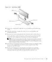
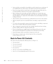
... load the rack from the rack. • Use caution when pressing the component rail release latches and sliding a component into the rack. • Do not overload the power supply branch circuit that provides power to components in a rack. Rack-to-Tower Kit Contents The rack-to-tower kit includes the following items (see Figure 1-1): • One tower bezel • One tower front panel •...
... load the rack from the rack. • Use caution when pressing the component rail release latches and sliding a component into the rack. • Do not overload the power supply branch circuit that provides power to components in a rack. Rack-to-Tower Kit Contents The rack-to-tower kit includes the following items (see Figure 1-1): • One tower bezel • One tower front panel •...

Rack-to-Tower Conversion Guide
Page 7
... are required to perform the conversion: • #2 Phillips screwdriver • 1/4-inch nut driver • Flat-tipped screwdriver • Torx T-10 driver (for removing and installing the front panels) Conversion Tasks Removing a system from the rack and removing the rack mounting hardware from the rack cabinet includes the following tasks: • Removing the rack doors • Removing the cable-management arm • Removing the system from the rack • Removing the bezel, cover...
... are required to perform the conversion: • #2 Phillips screwdriver • 1/4-inch nut driver • Flat-tipped screwdriver • Torx T-10 driver (for removing and installing the front panels) Conversion Tasks Removing a system from the rack and removing the rack mounting hardware from the rack cabinet includes the following tasks: • Removing the rack doors • Removing the cable-management arm • Removing the system from the rack • Removing the bezel, cover...
Rack-to-Tower Conversion Guide
Page 8
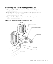
Figure 1-2. Removing the Cable-Management Arm captive thumbscrew cable-management arm Velcro strap back of the system (see Figure 1-2). Removing the Cable-Management Arm 1 Shut down and turn off the system you are converting as well as all peripherals attached to this system. 2 At the back of the rack cabinet, disconnect and remove the AC power cable and all other cables connected to the back of...
Figure 1-2. Removing the Cable-Management Arm captive thumbscrew cable-management arm Velcro strap back of the system (see Figure 1-2). Removing the Cable-Management Arm 1 Shut down and turn off the system you are converting as well as all peripherals attached to this system. 2 At the back of the rack cabinet, disconnect and remove the AC power cable and all other cables connected to the back of...
Rack-to-Tower Conversion Guide
Page 9
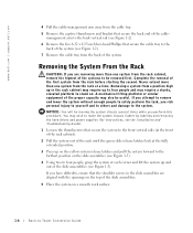
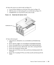
... on . NOTICE: You will be useful. You may wish to make the system chassis lighter by labeling and removing the hard drives and power supplies (for instructions, see the Installation and Troubleshooting Guide). 1 Loosen the thumbscrews that secure the system to the front vertical rails (at the front of the rack cabinet). 2 Pull the system out of the rack until the green slide release...
... on . NOTICE: You will be useful. You may wish to make the system chassis lighter by labeling and removing the hard drives and power supplies (for instructions, see the Installation and Troubleshooting Guide). 1 Loosen the thumbscrews that secure the system to the front vertical rails (at the front of the rack cabinet). 2 Pull the system out of the rack until the green slide release...
Rack-to-Tower Conversion Guide
Page 12
... front of the control-panel board. e Remove the control panel's interface cable. Removing the System Cover thumbscrews (3) 3 Remove the front panel: a Label and remove all power supplies (see your Installation and Troubleshooting Guide). d Remove the bezel connector cable from the system and set it aside. f Remove the four T-10 Torx screws that secure the rack front panel to the chassis. c Carefully lift the cover away from the center of the system (see your Installation and Troubleshooting Guide). c Remove the peripheral bay...
... front of the control-panel board. e Remove the control panel's interface cable. Removing the System Cover thumbscrews (3) 3 Remove the front panel: a Label and remove all power supplies (see your Installation and Troubleshooting Guide). d Remove the bezel connector cable from the system and set it aside. f Remove the four T-10 Torx screws that secure the rack front panel to the chassis. c Carefully lift the cover away from the center of the system (see your Installation and Troubleshooting Guide). c Remove the peripheral bay...

Rack-to-Tower Conversion Guide
Page 13
... control panel and screws aside for installation on a smooth work surface with the outside surface facing down. NOTICE: You will need two to four persons to the back of the trim panel with three 6-32 x 0.25-inch hex-head Phillips screws. 1-10 Rack-to leave the chassis in the rack position (as shown in Figure 1-6. www.dell.com | support.dell...
... control panel and screws aside for installation on a smooth work surface with the outside surface facing down. NOTICE: You will need two to four persons to the back of the trim panel with three 6-32 x 0.25-inch hex-head Phillips screws. 1-10 Rack-to leave the chassis in the rack position (as shown in Figure 1-6. www.dell.com | support.dell...
Rack-to-Tower Conversion Guide
Page 15
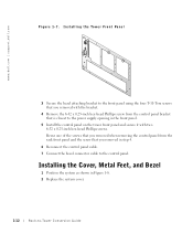
... power supply opening in step 4. 6 Reconnect the control panel cable. 7 Connect the bezel connector cable to -Tower Conversion Guide Reuse one of the screws that you removed when removing the control panel from the control panel bracket that you removed with two 6-32 x 0.25-inch hex-head Phillips screws. www.dell.com | support.dell.com Figure 1-7. Installing the Cover, Metal Feet, and Bezel 1 Position the system as shown in Figure 1-8. 2 Replace the system cover...
... power supply opening in step 4. 6 Reconnect the control panel cable. 7 Connect the bezel connector cable to -Tower Conversion Guide Reuse one of the screws that you removed when removing the control panel from the control panel bracket that you removed with two 6-32 x 0.25-inch hex-head Phillips screws. www.dell.com | support.dell.com Figure 1-7. Installing the Cover, Metal Feet, and Bezel 1 Position the system as shown in Figure 1-8. 2 Replace the system cover...
Rack-to-Tower Conversion Guide
Page 19
... a rack installation kit for the system you removed from the rack. Replacing the Rack Doors Refer to the procedures for replacing the rack doors in the documentation provided with screws, remove the screws that secure the front and back mounting-bracket flanges to -Tower Conversion Guide www.dell.com | support.dell.com...your rack cabinets. 1-16 Rack-to the vertical rails. 5 Repeat steps 1 through 3 (or step 4 if screws secure the slide assemblies) for the remaining slide assembly on the other side of the rack. 6 Place the cable-management arm, slide assemblies, and all fastener hardware in...
... a rack installation kit for the system you removed from the rack. Replacing the Rack Doors Refer to the procedures for replacing the rack doors in the documentation provided with screws, remove the screws that secure the front and back mounting-bracket flanges to -Tower Conversion Guide www.dell.com | support.dell.com...your rack cabinets. 1-16 Rack-to the vertical rails. 5 Repeat steps 1 through 3 (or step 4 if screws secure the slide assemblies) for the remaining slide assembly on the other side of the rack. 6 Place the cable-management arm, slide assemblies, and all fastener hardware in...
Removing the Back Fan Assembly
Page 1
... cables from the cooling shroud's retaining clips. See your Installation and Troubleshooting Guide for detailed information. 2 Remove the cooling shroud. Removing the Back Fan Assembly CAUTION: Only trained service technicians are authorized to remove the system cover and access any of the card, and lifting it straight up to clear the chassis. See your Installation and Troubleshooting Guide for detailed information. 3 Remove the memory riser cards by the extractor tabs, located...
... cables from the cooling shroud's retaining clips. See your Installation and Troubleshooting Guide for detailed information. 2 Remove the cooling shroud. Removing the Back Fan Assembly CAUTION: Only trained service technicians are authorized to remove the system cover and access any of the card, and lifting it straight up to clear the chassis. See your Installation and Troubleshooting Guide for detailed information. 3 Remove the memory riser cards by the extractor tabs, located...
Removing the Back Fan Assembly
Page 2
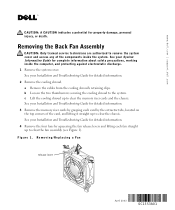
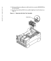
Removing the Back Fan Assembly release latch www.dell.com | support.dell.com 5 Disconnect the fan assembly power cable from the fan connector (REAR FANS) on the system board. 6 Press the release latch and lift the fan assembly straight up to clear the chassis (see Figure 2). Figure 2.
Removing the Back Fan Assembly release latch www.dell.com | support.dell.com 5 Disconnect the fan assembly power cable from the fan connector (REAR FANS) on the system board. 6 Press the release latch and lift the fan assembly straight up to clear the chassis (see Figure 2). Figure 2.
Removing the Back Fan Assembly
Page 3
... notice. © 2003 Dell Computer Corporation. a Lower the cooling shroud into position (see Figure 2). 2 Connect the fan assembly power cable to the system. www.dell.com | support.dell.com Replacing the Back Fan Assembly 1 Align the new fan assembly with the back fan assembly and the memory riser card cage. c Reroute the cables over the cooling shroud using the retaining clips. 6 Replace the system cover. All rights reserved.
... notice. © 2003 Dell Computer Corporation. a Lower the cooling shroud into position (see Figure 2). 2 Connect the fan assembly power cable to the system. www.dell.com | support.dell.com Replacing the Back Fan Assembly 1 Align the new fan assembly with the back fan assembly and the memory riser card cage. c Reroute the cables over the cooling shroud using the retaining clips. 6 Replace the system cover. All rights reserved.
Removing the Back Fan Assembly
Page 17
www.dell.com | support.dell.com 1 Installation and Troubleshooting Guide 2 a b 2 c Installation and Troubleshooting Guide 3 Installation and Troubleshooting Guide 4 4 1 2003 年 4 月
www.dell.com | support.dell.com 1 Installation and Troubleshooting Guide 2 a b 2 c Installation and Troubleshooting Guide 3 Installation and Troubleshooting Guide 4 4 1 2003 年 4 月


