Rack Installation Guide
Page 123
c 3 3 3 d 3 6-32 × e 12mm (0.5 ) f 6 a ( and Troubleshooting Guide ) b supplies installed in the system ( Installation and Troubleshooting Guide c CTRL_PNL d LED e LED f 10 Torx g h i 6-32 × ¼ Installation (Remove all power ) 4 T- 12 T-10 Torx 2 4-17
c 3 3 3 d 3 6-32 × e 12mm (0.5 ) f 6 a ( and Troubleshooting Guide ) b supplies installed in the system ( Installation and Troubleshooting Guide c CTRL_PNL d LED e LED f 10 Torx g h i 6-32 × ¼ Installation (Remove all power ) 4 T- 12 T-10 Torx 2 4-17
Rack-to-Tower Conversion Guide
Page 5
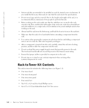
www.dell.com | support.dell.com • System rack kits are secured to the rack, extend to the floor, and that the full weight of a rack; If you install the ... the rack. • Use caution when pressing the component rail release latches and sliding a component into the rack. • Do not overload the power supply branch circuit that provides power to be sure that proper airflow is inserted into the rack, carefully extend the rail into a locking position, and then slide the component...
www.dell.com | support.dell.com • System rack kits are secured to the rack, extend to the floor, and that the full weight of a rack; If you install the ... the rack. • Use caution when pressing the component rail release latches and sliding a component into the rack. • Do not overload the power supply branch circuit that provides power to be sure that proper airflow is inserted into the rack, carefully extend the rail into a locking position, and then slide the component...
Rack-to-Tower Conversion Guide
Page 9
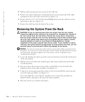
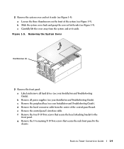
...rack cabinet may require up to four people and may wish to make the system chassis lighter by labeling and removing the hard drives and power supplies (for instructions, see the Installation and Troubleshooting Guide). 1 Loosen the thumbscrews that secure the system to the front vertical rails (at ... 1-3). 4 Using two to the system. Removing a system from a position high up and out of the slide asssemblies (see Figure 1-3). www.dell.com | support.dell.com 4 Pull the cable-management arm away from the cable tray. 5 Remove the captive thumbscrew and bracket that secure the back end of the...
...rack cabinet may require up to four people and may wish to make the system chassis lighter by labeling and removing the hard drives and power supplies (for instructions, see the Installation and Troubleshooting Guide). 1 Loosen the thumbscrews that secure the system to the front vertical rails (at ... 1-3). 4 Using two to the system. Removing a system from a position high up and out of the slide asssemblies (see Figure 1-3). www.dell.com | support.dell.com 4 Pull the cable-management arm away from the cable tray. 5 Remove the captive thumbscrew and bracket that secure the back end of the...
Rack-to-Tower Conversion Guide
Page 12
... lift the cover away from the center of the system (see Figure 1-5). Removing the System Cover thumbscrews (3) 3 Remove the front panel: a Label and remove all power supplies (see your Installation and Troubleshooting Guide). d Remove the bezel connector cable from the system and set it aside. g Remove the 14 remaining T-10 Torx screws...
... lift the cover away from the center of the system (see Figure 1-5). Removing the System Cover thumbscrews (3) 3 Remove the front panel: a Label and remove all power supplies (see your Installation and Troubleshooting Guide). d Remove the bezel connector cable from the system and set it aside. g Remove the 14 remaining T-10 Torx screws...
Rack-to-Tower Conversion Guide
Page 15
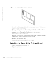
... on the tower front panel and secure it with two 6-32 x 0.25-inch hex-head Phillips screws. www.dell.com | support.dell.com Figure 1-7. Reuse one of the screws that is closest to the power supply opening in step 4. 6 Reconnect the control panel cable. 7 Connect the bezel connector cable to -Tower Conversion Guide Installing...
... on the tower front panel and secure it with two 6-32 x 0.25-inch hex-head Phillips screws. www.dell.com | support.dell.com Figure 1-7. Reuse one of the screws that is closest to the power supply opening in step 4. 6 Reconnect the control panel cable. 7 Connect the bezel connector cable to -Tower Conversion Guide Installing...
Rack-to-Tower Conversion Guide
Page 16
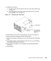
... retaining pins in the bezel's hinge halves. 6 Rotate the retaining pins in the drive bay (see your Installation and Troubleshooting Guide for instructions). 8 Reinstall the power supplies (see your Installation and Troubleshooting Guide for instructions). 9 Close the bezel. Rack-to the chassis and trim panel with four 6-32 x 0.25-inch hex-head...
... retaining pins in the bezel's hinge halves. 6 Rotate the retaining pins in the drive bay (see your Installation and Troubleshooting Guide for instructions). 8 Reinstall the power supplies (see your Installation and Troubleshooting Guide for instructions). 9 Close the bezel. Rack-to the chassis and trim panel with four 6-32 x 0.25-inch hex-head...


