Microprocessor Upgrade Installation Guide
Page 3
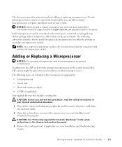
... off the system, including any peripherals, and disconnect the power cable from the electrical outlet. 2 Open the system doors, or remove the system cover (see your Installation and Troubleshooting Guide). The following items are contained in a pin-grid array (PGA) package that is installed in...system board, other ZIF sockets might be present to install or replace the microprocessor in a ZIF socket on the Dell Support website at support.dell.com, and upgrade the BIOS if necessary. Microprocessor Upgrade Installation Guide 1-1 This document provides instructions about adding or replacing...
... off the system, including any peripherals, and disconnect the power cable from the electrical outlet. 2 Open the system doors, or remove the system cover (see your Installation and Troubleshooting Guide). The following items are contained in a pin-grid array (PGA) package that is installed in...system board, other ZIF sockets might be present to install or replace the microprocessor in a ZIF socket on the Dell Support website at support.dell.com, and upgrade the BIOS if necessary. Microprocessor Upgrade Installation Guide 1-1 This document provides instructions about adding or replacing...
Microprocessor Upgrade Installation Guide
Page 6
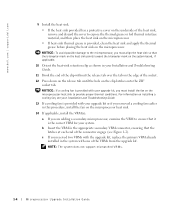
... in the appropriate secondary VRM connector, ensuring that the latches at each end of the connector engage (see your upgrade kit or if you removed a cooling fan earlier in this procedure, install the fan on the microprocessor heat sink. 14 If applicable, install the VRM(s): a If ... triangular mark on installing a cooling fan, see Figure 1-2). www.dell.com | support.dell.com 9 Install the heat sink. • If the heat sink provided has a protective cover on the underside of the heat sink, remove and discard the cover to expose the thermal grease or foil thermal interface material, and...
... in the appropriate secondary VRM connector, ensuring that the latches at each end of the connector engage (see your upgrade kit or if you removed a cooling fan earlier in this procedure, install the fan on the microprocessor heat sink. 14 If applicable, install the VRM(s): a If ... triangular mark on installing a cooling fan, see Figure 1-2). www.dell.com | support.dell.com 9 Install the heat sink. • If the heat sink provided has a protective cover on the underside of the heat sink, remove and discard the cover to expose the thermal grease or foil thermal interface material, and...
Rack-to-Tower Conversion Guide
Page 3
... Contents 1-2 Before You Begin 1-3 Recommended Tools 1-4 Conversion Tasks 1-4 Removing the Rack Doors 1-4 Removing the Cable-Management Arm 1-5 Removing the System From the Rack 1-6 Removing the Bezel, Cover, and Front Panel 1-8 Installing the Trim Panel 1-10 Installing the Front Panel 1-11 Installing the Cover, Metal Feet, and Bezel 1-12 Removing the Slide Assemblies 1-14 Replacing the Rack Doors...
... Contents 1-2 Before You Begin 1-3 Recommended Tools 1-4 Conversion Tasks 1-4 Removing the Rack Doors 1-4 Removing the Cable-Management Arm 1-5 Removing the System From the Rack 1-6 Removing the Bezel, Cover, and Front Panel 1-8 Installing the Trim Panel 1-10 Installing the Front Panel 1-11 Installing the Cover, Metal Feet, and Bezel 1-12 Removing the Slide Assemblies 1-14 Replacing the Rack Doors...

Rack-to-Tower Conversion Guide
Page 7
...dell.com | support.dell.com Recommended Tools The following tools are required to perform the conversion: • #2 Phillips screwdriver • 1/4-inch nut driver • Flat-tipped screwdriver • Torx T-10 driver (for removing and installing the front panels) Conversion Tasks Removing a system from the rack and removing...hardware from the rack cabinet includes the following tasks: • Removing the rack doors • Removing the cable-management arm • Removing the system from the rack • Removing the bezel, cover, and front panel • Installing the trim panel •...
...dell.com | support.dell.com Recommended Tools The following tools are required to perform the conversion: • #2 Phillips screwdriver • 1/4-inch nut driver • Flat-tipped screwdriver • Torx T-10 driver (for removing and installing the front panels) Conversion Tasks Removing a system from the rack and removing...hardware from the rack cabinet includes the following tasks: • Removing the rack doors • Removing the cable-management arm • Removing the system from the rack • Removing the bezel, cover, and front panel • Installing the trim panel •...
Rack-to-Tower Conversion Guide
Page 11
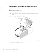
Removing the Front Bezel retaining pins c Squeeze the retaining pins and rotate them into their grooves to release the bezel. d Pull the bezel away and set ... 1-4. b Pivot the bezel away from the system until it aside. 1-8 Rack-to-Tower Conversion Guide www.dell.com | support.dell.com Removing the Bezel, Cover, and Front Panel This procedure is perpendicular to the system (see Figure 1-4). 1 Remove the bezel and set it is best performed with the system positioned as if it were in...
Removing the Front Bezel retaining pins c Squeeze the retaining pins and rotate them into their grooves to release the bezel. d Pull the bezel away and set ... 1-4. b Pivot the bezel away from the system until it aside. 1-8 Rack-to-Tower Conversion Guide www.dell.com | support.dell.com Removing the Bezel, Cover, and Front Panel This procedure is perpendicular to the system (see Figure 1-4). 1 Remove the bezel and set it is best performed with the system positioned as if it were in...
Rack-to-Tower Conversion Guide
Page 12
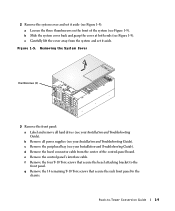
... Installation and Troubleshooting Guide). Rack-to the chassis. Figure 1-5. d Remove the bezel connector cable from the system and set it aside. Removing the System Cover thumbscrews (3) 3 Remove the front panel: a Label and remove all power supplies (see Figure 1-5). e Remove the control panel's interface cable. c Carefully lift the cover away from the center of the system (see your...
... Installation and Troubleshooting Guide). Rack-to the chassis. Figure 1-5. d Remove the bezel connector cable from the system and set it aside. Removing the System Cover thumbscrews (3) 3 Remove the front panel: a Label and remove all power supplies (see Figure 1-5). e Remove the control panel's interface cable. c Carefully lift the cover away from the center of the system (see your...
Rack-to-Tower Conversion Guide
Page 15
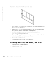
... the bezel connector cable to -Tower Conversion Guide www.dell.com | support.dell.com Figure 1-7. Reuse one of the screws that you removed when removing the control panel from the control panel bracket that you removed with two 6-32 x 0.25-inch hex-head Phillips screws. Installing the Cover, Metal Feet, and Bezel 1 Position the system as...
... the bezel connector cable to -Tower Conversion Guide www.dell.com | support.dell.com Figure 1-7. Reuse one of the screws that you removed when removing the control panel from the control panel bracket that you removed with two 6-32 x 0.25-inch hex-head Phillips screws. Installing the Cover, Metal Feet, and Bezel 1 Position the system as...
Removing the Back Fan Assembly
Page 1
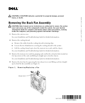
... top corners of the components inside the computer, and protecting against electrostatic discharge. 1 Remove the system cover. www.dell.com | support.dell.com CAUTION: A CAUTION indicates a potential for detailed information. 2 Remove the cooling shroud. a Remove the cables from the cooling shroud's retaining clips. Removing/Replacing a Fan release lever April 2003 0C1553A01 See your System Information Guide for...
... top corners of the components inside the computer, and protecting against electrostatic discharge. 1 Remove the system cover. www.dell.com | support.dell.com CAUTION: A CAUTION indicates a potential for detailed information. 2 Remove the cooling shroud. a Remove the cables from the cooling shroud's retaining clips. Removing/Replacing a Fan release lever April 2003 0C1553A01 See your System Information Guide for...


