
User Manual
Page 7
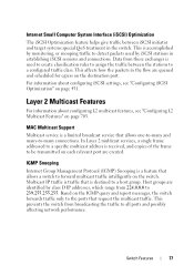
... (QoS) Features 76 Differentiated Services (DiffServ 76 Class Of Service (CoS 76 Auto Voice over IP (VoIP 76 Internet Small Computer System Interface (iSCSI) Optimization 77 Layer 2 Multicast Features 77 MAC Multicast Support 77 IGMP Snooping 77 IGMP Snooping Querier 78 MLD Snooping 78 Multicast VLAN Registration 78 Layer...Mode 79 Protocol Independent Multicast-Source Specific Multicast 79 Protocol Independent Multicast IPv6 Support . . . 79 MLD/MLDv2 (RFC2710/RFC3810 80 3 Hardware Overview 81 PowerConnect 7000 Series Front Panel 81 Switch Ports 84 Console Port 85 Contents 7
... (QoS) Features 76 Differentiated Services (DiffServ 76 Class Of Service (CoS 76 Auto Voice over IP (VoIP 76 Internet Small Computer System Interface (iSCSI) Optimization 77 Layer 2 Multicast Features 77 MAC Multicast Support 77 IGMP Snooping 77 IGMP Snooping Querier 78 MLD Snooping 78 Multicast VLAN Registration 78 Layer...Mode 79 Protocol Independent Multicast-Source Specific Multicast 79 Protocol Independent Multicast IPv6 Support . . . 79 MLD/MLDv2 (RFC2710/RFC3810 80 3 Hardware Overview 81 PowerConnect 7000 Series Front Panel 81 Switch Ports 84 Console Port 85 Contents 7

User Manual
Page 20
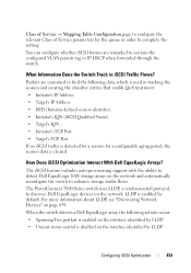
... 429 16 Configuring iSCSI Optimization 431 iSCSI Optimization Overview 431 When Should iSCSI Optimization Be Enabled 432 How Does the Switch Detect iSCSI Traffic Flows 432 How Is Quality of Service Applied to iSCSI Traffic Flows 432 What Information Does the Switch Track in iSCSI Traffic Flows 433 How Does iSCSI Optimization Interact With Dell EqualLogic Arrays 433...
... 429 16 Configuring iSCSI Optimization 431 iSCSI Optimization Overview 431 When Should iSCSI Optimization Be Enabled 432 How Does the Switch Detect iSCSI Traffic Flows 432 How Is Quality of Service Applied to iSCSI Traffic Flows 432 What Information Does the Switch Track in iSCSI Traffic Flows 433 How Does iSCSI Optimization Interact With Dell EqualLogic Arrays 433...

User Manual
Page 21
... Values 435 Configuring iSCSI Optimization (Web 436 iSCSI Global Configuration 436 iSCSI Targets Table 437 iSCSI Sessions Table 438 iSCSI Sessions Detailed 439 Configuring iSCSI Optimization (CLI 440 iSCSI Optimization Configuration Examples 442 Configuring iSCSI Optimization Between Servers and a Disk Array 442 17 Configuring a Captive Portal 445 Captive Portal Overview 445 What Does a Captive Portal Do 445 Is...
... Values 435 Configuring iSCSI Optimization (Web 436 iSCSI Global Configuration 436 iSCSI Targets Table 437 iSCSI Sessions Table 438 iSCSI Sessions Detailed 439 Configuring iSCSI Optimization (CLI 440 iSCSI Optimization Configuration Examples 442 Configuring iSCSI Optimization Between Servers and a Disk Array 442 17 Configuring a Captive Portal 445 Captive Portal Overview 445 What Does a Captive Portal Do 445 Is...
User Manual
Page 77
...relevant port are queued and scheduled for egress on the destination port. For information about configuring L2 multicast features, see "Configuring iSCSI Optimization" on page 703. Host groups are identified by class D IP addresses, which range from 224.0.0.0 to the ports ... used by monitoring, or snooping traffic to all ports and possibly affecting network performance. Internet Small Computer System Interface (iSCSI) Optimization The iSCSI Optimization feature helps give traffic between the stations to a configured traffic class. Data from broadcasting the traffic to detect ...
...relevant port are queued and scheduled for egress on the destination port. For information about configuring L2 multicast features, see "Configuring iSCSI Optimization" on page 703. Host groups are identified by class D IP addresses, which range from 224.0.0.0 to the ports ... used by monitoring, or snooping traffic to all ports and possibly affecting network performance. Internet Small Computer System Interface (iSCSI) Optimization The iSCSI Optimization feature helps give traffic between the stations to a configured traffic class. Data from broadcasting the traffic to detect ...

User Manual
Page 114
... OSPF Router ID IP Helper and UDP Relay RIP VRRP Tunnel and Loopback Interfaces IPv6 Routing DHCPv6 OSPFv3 DiffServ Auto VoIP Auto VoIP Traffic Class iSCSI Bridge Multicast Filtering MLD Snooping IGMP Snooping IGMP Snooping Querier GMRP IPv4 Multicast IPv6 Multicast Default No LAGs configured 1 Disabled Enabled 0.0.0.0 Enabled Enabled Disabled None...
... OSPF Router ID IP Helper and UDP Relay RIP VRRP Tunnel and Loopback Interfaces IPv6 Routing DHCPv6 OSPFv3 DiffServ Auto VoIP Auto VoIP Traffic Class iSCSI Bridge Multicast Filtering MLD Snooping IGMP Snooping IGMP Snooping Querier GMRP IPv4 Multicast IPv6 Multicast Default No LAGs configured 1 Disabled Enabled 0.0.0.0 Enabled Enabled Disabled None...
User Manual
Page 143
... does not divide the stack into multiple stacks. A stack of disruption to other biconnected topology), so that Checkpoint Data Application IGMP/MLD Snooping IPv6 NDP iSCSI LLDP OSPFv2 OSPFv3 Route Table Manager SIM Voice VLAN Checkpointed Data Multicast groups, list of router ports, last query data for the service port, network...
... does not divide the stack into multiple stacks. A stack of disruption to other biconnected topology), so that Checkpoint Data Application IGMP/MLD Snooping IPv6 NDP iSCSI LLDP OSPFv2 OSPFv3 Route Table Manager SIM Voice VLAN Checkpointed Data Multicast groups, list of router ports, last query data for the service port, network...

User Manual
Page 165
... the failover occurs, the exchange is interrupted while the control plane restarts. There are two iSCSI connections as follows: Session A: 10.1.1.10 to 10.1.1.3 Session B: 10.1.1.11 to 10.1.1.1 An iSCSI application running on untrusted ports. NSF and the Storage Access Network Figure 8-15 illustrates a...snooping does not miss any new bindings during the restart. If a host is in the middle of three PowerConnect switches connecting two servers (iSCSI initiators) to a disk array (iSCSI targets). When DHCP snooping is enabled on the access switch, the hardware traps ARP packets to the CPU on...
... the failover occurs, the exchange is interrupted while the control plane restarts. There are two iSCSI connections as follows: Session A: 10.1.1.10 to 10.1.1.3 Session B: 10.1.1.11 to 10.1.1.1 An iSCSI application running on untrusted ports. NSF and the Storage Access Network Figure 8-15 illustrates a...snooping does not miss any new bindings during the restart. If a host is in the middle of three PowerConnect switches connecting two servers (iSCSI initiators) to a disk array (iSCSI targets). When DHCP snooping is enabled on the access switch, the hardware traps ARP packets to the CPU on...

User Manual
Page 166
... unit, the new session receives no priority treatment in the hardware. 166 Managing a Switch Stack NSF and a Storage Area Network Disc Array (iSCSI Targets) 10.1.1.2 10.1.1.3 10.1.1.1 Servers (iSCSI Initiators) 10.1.1.10 10.1.1.11 When the Management Unit fails, session A drops. The hardware forwards the packets to establish this new session, but...
... unit, the new session receives no priority treatment in the hardware. 166 Managing a Switch Stack NSF and a Storage Area Network Disc Array (iSCSI Targets) 10.1.1.2 10.1.1.3 10.1.1.1 Servers (iSCSI Initiators) 10.1.1.10 10.1.1.11 When the Management Unit fails, session A drops. The hardware forwards the packets to establish this new session, but...

User Manual
Page 431
... 431 The traffic classification affects how the packets in this chapter include: • iSCSI Optimization Overview • Default iSCSI Optimization Values • Configuring iSCSI Optimization (Web) • Configuring iSCSI Optimization (CLI) • iSCSI Optimization Configuration Examples iSCSI Optimization Overview iSCSI optimization provides a means of giving special Quality of service (QoS) treatment for egress on the switch. This...
... 431 The traffic classification affects how the packets in this chapter include: • iSCSI Optimization Overview • Default iSCSI Optimization Values • Configuring iSCSI Optimization (Web) • Configuring iSCSI Optimization (CLI) • iSCSI Optimization Configuration Examples iSCSI Optimization Overview iSCSI optimization provides a means of giving special Quality of service (QoS) treatment for egress on the switch. This...

User Manual
Page 432
...policy is applied to packets in the status tables, but no CoS policy is enabled, by installing classifier rules that would otherwise cause iSCSI packets to be balanced against the needs of other data traveling through the switch. You can be given the desired preference characteristics over...by giving it preferential QoS treatment. The dynamically-generated classifier rules are detected and shown in detected iSCSI sessions. How Does the Switch Detect iSCSI Traffic Flows? By default, iSCSI flows are assigned to the highest VLAN priority tag or DSCP value mapped to the highest queue ...
...policy is applied to packets in the status tables, but no CoS policy is enabled, by installing classifier rules that would otherwise cause iSCSI packets to be balanced against the needs of other data traveling through the switch. You can be given the desired preference characteristics over...by giving it preferential QoS treatment. The dynamically-generated classifier rules are detected and shown in detected iSCSI sessions. How Does the Switch Detect iSCSI Traffic Flows? By default, iSCSI flows are assigned to the highest VLAN priority tag or DSCP value mapped to the highest queue ...
User Manual
Page 433
... portfast is enabled on page 659. The PowerConnect 7000 Series switch uses LLDP, a vendor-neutral protocol, to discover Dell EqualLogic devices on the network and automatically reconfigure the switch to enhance storage traffic flows. Configuring iSCSI Optimization 433 How Does iSCSI Optimization Interact With Dell EqualLogic Arrays? The iSCSI feature includes auto-provisioning support with the...
... portfast is enabled on page 659. The PowerConnect 7000 Series switch uses LLDP, a vendor-neutral protocol, to discover Dell EqualLogic devices on the network and automatically reconfigure the switch to enhance storage traffic flows. Configuring iSCSI Optimization 433 How Does iSCSI Optimization Interact With Dell EqualLogic Arrays? The iSCSI feature includes auto-provisioning support with the...

User Manual
Page 434
...the detection of enabling iSCSI. 434 Configuring iSCSI Optimization Disabling iSCSI does not remove the MTU, flow control, portfast or storm control configuration applied as a result of Dell EqualLogic arrays by using LLDP is disabled. If the iSCSI feature is disabled on the switch, iSCSI resources are enabled).... • Flow control is globally enabled, if it is not already enabled. • iSCSI LLDP monitoring starts to the ...
...the detection of enabling iSCSI. 434 Configuring iSCSI Optimization Disabling iSCSI does not remove the MTU, flow control, portfast or storm control configuration applied as a result of Dell EqualLogic arrays by using LLDP is disabled. If the iSCSI feature is disabled on the switch, iSCSI resources are enabled).... • Flow control is globally enabled, if it is not already enabled. • iSCSI LLDP monitoring starts to the ...

User Manual
Page 435
... VLAN instead of by default the highest 802.1p VLAN priority tag mapped to the highest queue not used for the iSCSI optimization feature. Non configured. 10 minutes iSCSI well-known ports 3260 and 860 are configured as default (with no IP address or name) but can be removed ...as the classification, iSCSI flows are assigned by DSCP values. Configuring iSCSI Optimization 435 Table 16-1. Default iSCSI Optimization Values Table 16-1 shows the default values for stack management or the voice VLAN. When DSCP is...
... VLAN instead of by default the highest 802.1p VLAN priority tag mapped to the highest queue not used for the iSCSI optimization feature. Non configured. 10 minutes iSCSI well-known ports 3260 and 860 are configured as default (with no IP address or name) but can be removed ...as the classification, iSCSI flows are assigned by DSCP values. Configuring iSCSI Optimization 435 Table 16-1. Default iSCSI Optimization Values Table 16-1 shows the default values for stack management or the voice VLAN. When DSCP is...
User Manual
Page 436
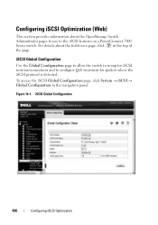
... configure QoS treatment for packets where the iSCSI protocol is detected. Configuring iSCSI Optimization (Web) This section provides information about the fields on a PowerConnect 7000 Series switch. iSCSI Global Configuration Use the Global Configuration page to allow the switch to snoop for iSCSI sessions/connections and to the iSCSI features on a page, click at the top...
... configure QoS treatment for packets where the iSCSI protocol is detected. Configuring iSCSI Optimization (Web) This section provides information about the fields on a PowerConnect 7000 Series switch. iSCSI Global Configuration Use the Global Configuration page to allow the switch to snoop for iSCSI sessions/connections and to the iSCSI features on a page, click at the top...

User Manual
Page 437
Figure 16-2. Figure 16-3. Add iSCSI Targets Configuring iSCSI Optimization 437 iSCSI Targets Table Use the Targets Table page to view and configure iSCSI targets on the switch. iSCSI Targets Table To add an iSCSI Target, click Add at the top of the page and configure the relevant information about the iSCSI target. To access the Targets Table page, click System → iSCSI → Targets in the navigation panel.
Figure 16-2. Figure 16-3. Add iSCSI Targets Configuring iSCSI Optimization 437 iSCSI Targets Table Use the Targets Table page to view and configure iSCSI targets on the switch. iSCSI Targets Table To add an iSCSI Target, click Add at the top of the page and configure the relevant information about the iSCSI target. To access the Targets Table page, click System → iSCSI → Targets in the navigation panel.

User Manual
Page 438
Figure 16-4. To access the Sessions Table page, click System → iSCSI → Sessions Table in the navigation panel. The maximum number of iSCSI sessions is 192. iSCSI Sessions Table Use the Sessions Table page to view summary information about the iSCSI sessions that the switch has discovered. iSCSI Sessions Table 438 Configuring iSCSI Optimization An iSCSI session occurs when an iSCSI initiator and iSCSI target communicate over one or more TCP connections.
Figure 16-4. To access the Sessions Table page, click System → iSCSI → Sessions Table in the navigation panel. The maximum number of iSCSI sessions is 192. iSCSI Sessions Table Use the Sessions Table page to view summary information about the iSCSI sessions that the switch has discovered. iSCSI Sessions Table 438 Configuring iSCSI Optimization An iSCSI session occurs when an iSCSI initiator and iSCSI target communicate over one or more TCP connections.

User Manual
Page 439
iSCSI Sessions Detail Configuring iSCSI Optimization 439 Figure 16-5. iSCSI Sessions Detailed Use the Sessions Detailed page to view detailed information about an iSCSI sessions that the switch has discovered. To access the Sessions Detailed page, click System → iSCSI → Sessions Detailed in the navigation panel.
iSCSI Sessions Detail Configuring iSCSI Optimization 439 Figure 16-5. iSCSI Sessions Detailed Use the Sessions Detailed page to view detailed information about an iSCSI sessions that the switch has discovered. To access the Sessions Detailed page, click System → iSCSI → Sessions Detailed in the navigation panel.
User Manual
Page 440
... ports can be statically configured; Up to assign received iSCSI session packets. • remark-Mark the iSCSI frames with the configured DSCP value when egressing the switch. 440 Configuring iSCSI Optimization iscsi enable Globally enable iSCSI optimization. Command Purpose configure Enter Global Configuration mode. When... deleted is one command or by using multiple commands. • ip-address-IP address of the iSCSI target. Configuring iSCSI Optimization (CLI) This section provides information about the commands, see the PowerConnect 7000 Series CLI Reference Guide.
... ports can be statically configured; Up to assign received iSCSI session packets. • remark-Mark the iSCSI frames with the configured DSCP value when egressing the switch. 440 Configuring iSCSI Optimization iscsi enable Globally enable iSCSI optimization. Command Purpose configure Enter Global Configuration mode. When... deleted is one command or by using multiple commands. • ip-address-IP address of the iSCSI target. Configuring iSCSI Optimization (CLI) This section provides information about the commands, see the PowerConnect 7000 Series CLI Reference Guide.
User Manual
Page 441
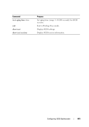
Exit to Privilege Exec mode. Display iSCSI session information. Command iscsi aging time time exit show iscsi show iscsi sessions Purpose Set aging time (range: 1-43,200 seconds) for iSCSI sessions. Configuring iSCSI Optimization 441 Display iSCSI settings.
Exit to Privilege Exec mode. Display iSCSI session information. Command iscsi aging time time exit show iscsi show iscsi sessions Purpose Set aging time (range: 1-43,200 seconds) for iSCSI sessions. Configuring iSCSI Optimization 441 Display iSCSI settings.

User Manual
Page 442
... treatment when forwarded in the diagram) has installed priority filters to a disk array (iSCSI targets). Configuring iSCSI Optimization Between Servers and a Disk Array Figure 16-6 illustrates a stack of three PowerConnect 7000 Series switches connecting two servers (iSCSI initiators) to ensure that iSCSI traffic that is part of switches that are between a disk array and servers...
... treatment when forwarded in the diagram) has installed priority filters to a disk array (iSCSI targets). Configuring iSCSI Optimization Between Servers and a Disk Array Figure 16-6 illustrates a stack of three PowerConnect 7000 Series switches connecting two servers (iSCSI initiators) to ensure that iSCSI traffic that is part of switches that are between a disk array and servers...


