User Manual
Page 4
... High Port Count 56 Single IP Management 56 Automatic Firmware Upgrade for New Stack Members 56 Stacking Compatibility with the PowerConnect M6348 56 Master Failover with Transparent Transition . . . . 57 Nonstop Forwarding on the Stack 57 Hot Add/Delete and Firmware Synchronization 57 Security Features 57 Configurable Access and Authentication Profiles 57 Password-Protected Management...
... High Port Count 56 Single IP Management 56 Automatic Firmware Upgrade for New Stack Members 56 Stacking Compatibility with the PowerConnect M6348 56 Master Failover with Transparent Transition . . . . 57 Nonstop Forwarding on the Stack 57 Hot Add/Delete and Firmware Synchronization 57 Security Features 57 Configurable Access and Authentication Profiles 57 Password-Protected Management...
User Manual
Page 8
Out-of-Band Management Port 85 USB Port 85 Reset Button 86 Port and System LEDs 86 Stack Master LED and Stack Number Display . . . 86 PowerConnect 7000 Series Back Panel 87 Expansion Slots for Plug-in Modules 88 Power Supplies 89 Ventilation System 90 ...Locator LED 90 LED Definitions 91 Port LEDs 91 Module LEDs 93 System LEDs 95 4 Using Dell OpenManage Switch Administrator 97 About Dell OpenManage Switch Administrator. ...
Out-of-Band Management Port 85 USB Port 85 Reset Button 86 Port and System LEDs 86 Stack Master LED and Stack Number Display . . . 86 PowerConnect 7000 Series Back Panel 87 Expansion Slots for Plug-in Modules 88 Power Supplies 89 Ventilation System 90 ...Locator LED 90 LED Definitions 91 Port LEDs 91 Module LEDs 93 System LEDs 95 4 Using Dell OpenManage Switch Administrator 97 About Dell OpenManage Switch Administrator. ...
User Manual
Page 10
... Network Information Configuration Example 132 8 Managing a Switch Stack 135 Stacking Overview 135 PowerConnect 7000 Series and M6348 Stacking Compatibility 137 How is the Management Unit Selected? . . . . . 137 Adding a Switch to the Stack 138 Removing a Switch from the Stack 139 How is the Firmware Updated on the Stack?. . . 140 What is Stacking Standby 140 What is Nonstop Forwarding 140...
... Network Information Configuration Example 132 8 Managing a Switch Stack 135 Stacking Overview 135 PowerConnect 7000 Series and M6348 Stacking Compatibility 137 How is the Management Unit Selected? . . . . . 137 Adding a Switch to the Stack 138 Removing a Switch from the Stack 139 How is the Firmware Updated on the Stack?. . . 140 What is Stacking Standby 140 What is Nonstop Forwarding 140...
User Manual
Page 11
... Considerations 144 Why is Stacking Needed 144 Default Stacking Values 145 Managing and Monitoring the Stack (Web 146 Unit Configuration 146 Stack Summary 148 Stack Firmware Synchronization 149 Supported Switches 150 Stack Port Summary 151 Stack Port Counters 152 Stack Port Diagnostics 152 NSF Summary 153 Checkpoint Statistics 154 Managing the Stack (CLI 155 Configuring Stack Member and NSF Settings...
... Considerations 144 Why is Stacking Needed 144 Default Stacking Values 145 Managing and Monitoring the Stack (Web 146 Unit Configuration 146 Stack Summary 148 Stack Firmware Synchronization 149 Supported Switches 150 Stack Port Summary 151 Stack Port Counters 152 Stack Port Diagnostics 152 NSF Summary 153 Checkpoint Statistics 154 Managing the Stack (CLI 155 Configuring Stack Member and NSF Settings...
User Manual
Page 34
... 837 How Is the Address Table Populated 837 What Information Is in the MAC Address Table 838 How Is the MAC Address Table Maintained Across a Stack 838 Default MAC Address Table Values 838 Managing the MAC Address Table (Web 839 Static Address Table 839 Dynamic Address Table 841 Managing the MAC...
... 837 How Is the Address Table Populated 837 What Information Is in the MAC Address Table 838 How Is the MAC Address Table Maintained Across a Stack 838 Default MAC Address Table Values 838 Managing the MAC Address Table (Web 839 Static Address Table 839 Dynamic Address Table 841 Managing the MAC...
User Manual
Page 49
.... • High availability with hot swappable stack members. Introduction 49 About This Document This guide describes how to configure, monitor, and maintain a Dell PowerConnect 7000 Series switch by using Web-based Dell OpenManage Switch Administrator utility or the command-line...mountable chassis design. • Support for all data-communication requirements for network administrators in the Dell PowerConnect 7000 Series are stackable Layer 2 and 3 switches that extend the Dell PowerConnect LAN switching product range. Audience This guide is for a multi-layer switch, including layer...
.... • High availability with hot swappable stack members. Introduction 49 About This Document This guide describes how to configure, monitor, and maintain a Dell PowerConnect 7000 Series switch by using Web-based Dell OpenManage Switch Administrator utility or the command-line...mountable chassis design. • Support for all data-communication requirements for network administrators in the Dell PowerConnect 7000 Series are stackable Layer 2 and 3 switches that extend the Dell PowerConnect LAN switching product range. Audience This guide is for a multi-layer switch, including layer...

User Manual
Page 51
... 2 Multicast Features s • Layer 3 Multicast Features p Switch Features 51 NOTE: Before proceeding, read the release notes for this section include: • System Management Features • Stacking Features • Security Features • Green Technology Features • Power over Ethernet (PoE) Plus Features • Switching Features • Virtual Local Area Network Supported Features...
... 2 Multicast Features s • Layer 3 Multicast Features p Switch Features 51 NOTE: Before proceeding, read the release notes for this section include: • System Management Features • Stacking Features • Security Features • Green Technology Features • Power over Ethernet (PoE) Plus Features • Switching Features • Virtual Local Area Network Supported Features...
User Manual
Page 56
... an older version of the firmware than the other stack members, the firmware on page 135. Stacking Compatibility with a larger port count. The stack operates and is running the same firmware version. Stacking Features For information about creating and maintaining a stack of the master unit. The stack can stack PowerConnect 7000 Series switches up to 12 switches high...
... an older version of the firmware than the other stack members, the firmware on page 135. Stacking Compatibility with a larger port count. The stack operates and is running the same firmware version. Stacking Features For information about creating and maintaining a stack of the master unit. The stack can stack PowerConnect 7000 Series switches up to 12 switches high...
User Manual
Page 57
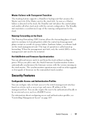
...access type and source IP address of the management host. When you add a unit, the Stack Firmware Synchronization feature automatically synchronizes the firmware version with Transparent Transition The stacking feature supports a Standby or backup unit that assumes the Master unit role if the Master unit ...You can configure rules to limit access to be restarted. As soon as a result of stack units to continue to and from the stack without cycling the power. Nonstop Forwarding on the Stack The Nonstop Forwarding (NSF) feature allows the forwarding plane of a power failure, hardware ...
...access type and source IP address of the management host. When you add a unit, the Stack Firmware Synchronization feature automatically synchronizes the firmware version with Transparent Transition The stacking feature supports a Standby or backup unit that assumes the Master unit role if the Master unit ...You can configure rules to limit access to be restarted. As soon as a result of stack units to continue to and from the stack without cycling the power. Nonstop Forwarding on the Stack The Nonstop Forwarding (NSF) feature allows the forwarding plane of a power failure, hardware ...
User Manual
Page 75
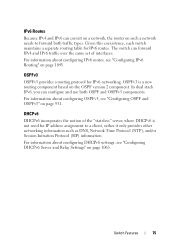
For information about configuring IPv6 routes, see "Configuring IPv6 Routing" on page 931. In dual stack IPv6, you can configure and use both traffic types. For information about configuring DHCPv6 settings, see "Configuring OSPF and OSPFv3" on page 1045. OSPFv3 OSPFv3 ...
For information about configuring IPv6 routes, see "Configuring IPv6 Routing" on page 931. In dual stack IPv6, you can configure and use both traffic types. For information about configuring DHCPv6 settings, see "Configuring OSPF and OSPFv3" on page 1045. OSPFv3 OSPFv3 ...
User Manual
Page 81
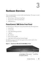
...; Out-of-Band Management Port • USB Port • Reset Button • Port and System LEDs • Stack Master LED and Stack Number Display The following images show the front panels of the switch hardware. PowerConnect 7024 with 24 10/100/1000Base-T Ports 10/100/1000Base-T Auto-sensing Combo Ports Full Duplex RJ-45...
...; Out-of-Band Management Port • USB Port • Reset Button • Port and System LEDs • Stack Master LED and Stack Number Display The following images show the front panels of the switch hardware. PowerConnect 7024 with 24 10/100/1000Base-T Ports 10/100/1000Base-T Auto-sensing Combo Ports Full Duplex RJ-45...

User Manual
Page 86
... information about the status that indicate the status of a stack, the M LED is illuminated and the stack unit number is 1. 86 Hardware Overview panel displays the unit number for the stack member. Reset Button The reset button is solid green. Additionally, the PowerConnect 7024P and PowerConnect 7048P switches contain LEDs that were not saved to...
... information about the status that indicate the status of a stack, the M LED is illuminated and the stack unit number is 1. 86 Hardware Overview panel displays the unit number for the stack member. Reset Button The reset button is solid green. Additionally, the PowerConnect 7024P and PowerConnect 7048P switches contain LEDs that were not saved to...
User Manual
Page 87
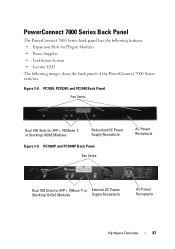
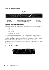
... • Locator LED The following images show the back panel of the PowerConnect 7000 Series switches. PowerConnect 7000 Series Back Panel The PowerConnect 7000 Series back panel has the following features: • Expansion Slots for SFP+, 10Base-T, or External DC Power Stacking/10 GbE Modules Supply Receptacle AC Power Receptacle Hardware Overview 87 PC7024...
... • Locator LED The following images show the back panel of the PowerConnect 7000 Series switches. PowerConnect 7000 Series Back Panel The PowerConnect 7000 Series back panel has the following features: • Expansion Slots for SFP+, 10Base-T, or External DC Power Stacking/10 GbE Modules Supply Receptacle AC Power Receptacle Hardware Overview 87 PC7024...
User Manual
Page 88
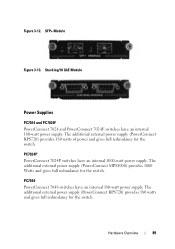
The following modules: • 10GBase-T module • SFP+ module • Stacking/10 GbE module Each plug-in module has two ports. The plug-in Modules Two expansion slots are located on the back of the switch ... Overview Figure 3-10. PC7048R Back Panel Fan Trays AC Power Receptacle Dual 10G Slots for SFP+, 10GBase-T, or Stacking/10GbE Modules AC Power Receptacle Expansion Slots for the PowerConnect 7000 Series switches. The Stacking/10GbE modules can support the following figures show the modules available for Plug-in modules include hot-swap support...
The following modules: • 10GBase-T module • SFP+ module • Stacking/10 GbE module Each plug-in module has two ports. The plug-in Modules Two expansion slots are located on the back of the switch ... Overview Figure 3-10. PC7048R Back Panel Fan Trays AC Power Receptacle Dual 10G Slots for SFP+, 10GBase-T, or Stacking/10GbE Modules AC Power Receptacle Expansion Slots for the PowerConnect 7000 Series switches. The Stacking/10GbE modules can support the following figures show the modules available for Plug-in modules include hot-swap support...
User Manual
Page 89
Hardware Overview 89 SFP+ Module Figure 3-13. PC7024P PowerConnect 7024P switches have an internal 180-watt power supply. The additional external power supply (PowerConnect RPS720) provides 180 watts of power and gives full redundancy for the switch. Stacking/10 GbE Module Power Supplies PC7024 and PC7024F PowerConnect 7024 and PowerConnect 7024F switches have an internal 1000-watt...
Hardware Overview 89 SFP+ Module Figure 3-13. PC7024P PowerConnect 7024P switches have an internal 180-watt power supply. The additional external power supply (PowerConnect RPS720) provides 180 watts of power and gives full redundancy for the switch. Stacking/10 GbE Module Power Supplies PC7024 and PC7024F PowerConnect 7024 and PowerConnect 7024F switches have an internal 1000-watt...
User Manual
Page 93
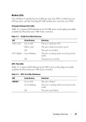
... blinking Off Definition The port is not linked. SFP+ Port LEDs Table 3-5 contains LED definitions for SFP+ port on the plug-in module available for PowerConnect 7000 Series switches. The port is linked. The port is linked at 10G. The port has no activity. Module LEDs The 10GBase-T module has two... LEDs per port, the SFP+ module has one LED per port, and the Stacking/10 GbE module does not have any LEDs. 10 Gigabit Ethernet Port LEDs Table 3-4 contains LED definitions for 10 GbE ports on the plug-in...
... blinking Off Definition The port is not linked. SFP+ Port LEDs Table 3-5 contains LED definitions for SFP+ port on the plug-in module available for PowerConnect 7000 Series switches. The port is linked. The port is linked at 10G. The port has no activity. Module LEDs The 10GBase-T module has two... LEDs per port, the SFP+ module has one LED per port, and the Stacking/10 GbE module does not have any LEDs. 10 Gigabit Ethernet Port LEDs Table 3-4 contains LED definitions for 10 GbE ports on the plug-in...
User Manual
Page 95
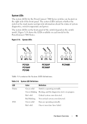
... the diagnostics test is operating normally. System LED Definitions LED Status FAN Color Definition Green solid Switch is in the PowerConnect 7000 Series. The system LEDs indicate whether the switch is the stack master and provide information about the status of the front panel. System LEDs PWR Status PWR Status PWR1 Status...
... the diagnostics test is operating normally. System LED Definitions LED Status FAN Color Definition Green solid Switch is in the PowerConnect 7000 Series. The system LEDs indicate whether the switch is the stack master and provide information about the status of the front panel. System LEDs PWR Status PWR Status PWR1 Status...

User Manual
Page 96
... operating correctly. EPS Green solid External power supply is detected. Off No external power supply is operating normally. M Green solid Master switch for the stack. Off Non-master stack unit. Red solid A redundant power supply is detected, but it is not operating correctly Off No redundant power supply is operating normally. System... first power supply, and the PWR2 LEDs indicates the status of the second power supply. 96 Hardware Overview Table 3-8. A standalone switch is operating normally. The PowerConnect 7048R has two power supplies.
... operating correctly. EPS Green solid External power supply is detected. Off No external power supply is operating normally. M Green solid Master switch for the stack. Off Non-master stack unit. Red solid A redundant power supply is detected, but it is not operating correctly Off No redundant power supply is operating normally. System... first power supply, and the PWR2 LEDs indicates the status of the second power supply. 96 Hardware Overview Table 3-8. A standalone switch is operating normally. The PowerConnect 7048R has two power supplies.
User Manual
Page 103
...to access the device must have an IP address, and the management station you use the Command-Line Interface (CLI) on a PowerConnect 7000 Series switch. NOTE: For a stack of the front panel and is illuminated on page 115. For more information about assigning an IP address to a switch, see... the Getting Started Guide available at support.dell.com/manuals. 1 Connect the DB-9 connector of the supplied serial cable to a management station, ...
...to access the device must have an IP address, and the management station you use the Command-Line Interface (CLI) on a PowerConnect 7000 Series switch. NOTE: For a stack of the front panel and is illuminated on page 115. For more information about assigning an IP address to a switch, see... the Getting Started Guide available at support.dell.com/manuals. 1 Connect the DB-9 connector of the supplied serial cable to a management station, ...
User Manual
Page 104
... four simultaneous Telnet sessions. None • Stop bits - 1 • Flow control - You can also initiate a Telnet session from the Web Interface" on the switch (or stack). To connect to the switch. You can use any Telnet client on the management station to connect to the switch by using Telnet, the switch...
... four simultaneous Telnet sessions. None • Stop bits - 1 • Flow control - You can also initiate a Telnet session from the Web Interface" on the switch (or stack). To connect to the switch. You can use any Telnet client on the management station to connect to the switch by using Telnet, the switch...


