User's Guide
Page 3
Contents 1 Introduction 11 System Description 11 PowerConnect 3524 11 PowerConnect 3524P 11 PowerConnect 3548 12 PowerConnect 3548P 12 Stacking Overview 12 Understanding the Stack Topology 13 Stacking Failover Topology 13 Stacking Members and Unit ID 13 Removing and Replacing Stacking Members 14 ...
Contents 1 Introduction 11 System Description 11 PowerConnect 3524 11 PowerConnect 3524P 11 PowerConnect 3548 12 PowerConnect 3548P 12 Stacking Overview 12 Understanding the Stack Topology 13 Stacking Failover Topology 13 Stacking Members and Unit ID 13 Removing and Replacing Stacking Members 14 ...
User's Guide
Page 11
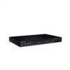
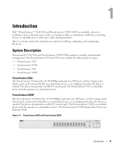
...: • PowerConnect 3524 • PowerConnect 3524P • PowerConnect 3548 • PowerConnect 3548P PowerConnect 3524 The PowerConnect 3524 provides 24 10/100Mbps ports plus two SFP ports, and two Copper ports which can be used to forward traffic in a stand-alone device, or as stacking ports when the device is stacked. Introduction Dell™ PowerConnect™ 3524/3548 and PowerConnect 3524P/3548P are stackable...
...: • PowerConnect 3524 • PowerConnect 3524P • PowerConnect 3548 • PowerConnect 3548P PowerConnect 3524 The PowerConnect 3524 provides 24 10/100Mbps ports plus two SFP ports, and two Copper ports which can be used to forward traffic in a stand-alone device, or as stacking ports when the device is stacked. Introduction Dell™ PowerConnect™ 3524/3548 and PowerConnect 3524P/3548P are stackable...

User's Guide
Page 12
... be used to forward traffic when the device is in a stand-alone device, or as stack members, and assigned a unique Unit ID. PowerConnect 3548 and PowerConnect 3548P Stacking Overview PowerConnect 3524/P and PowerConnect 3548/P stacking provides multiple switch management through which can be running the same software version. During the Stacking setup, one switch is a stackable device...
... be used to forward traffic when the device is in a stand-alone device, or as stack members, and assigned a unique Unit ID. PowerConnect 3548 and PowerConnect 3548P Stacking Overview PowerConnect 3524/P and PowerConnect 3548/P stacking provides multiple switch management through which can be running the same software version. During the Stacking setup, one switch is a stackable device...
User's Guide
Page 32
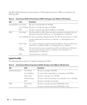
...PD is being detected, or is running at normal load. Gigabit Port LEDs The following table: Table 2-2. PowerConnect 3524 and PowerConnect 3548 RJ-45 Copper based 100BaseT LED Indications LED Link/Activity/Speed FDX Color Green Static Green Flashing Yellow Static Yellow... linked at transitional mode. The RJ-45 LED indications for PowerConnect 3524P and PowerConnect 3548P are described in the following table describes the Gigabit (stacking port) LEDs: Table 2-3. PowerConnect 3524P and PowerConnect 3548P RJ-45 Copper based 100BaseT LED Indications LED Color Description Speed...
...PD is being detected, or is running at normal load. Gigabit Port LEDs The following table: Table 2-2. PowerConnect 3524 and PowerConnect 3548 RJ-45 Copper based 100BaseT LED Indications LED Link/Activity/Speed FDX Color Green Static Green Flashing Yellow Static Yellow... linked at transitional mode. The RJ-45 LED indications for PowerConnect 3524P and PowerConnect 3548P are described in the following table describes the Gigabit (stacking port) LEDs: Table 2-3. PowerConnect 3524P and PowerConnect 3548P RJ-45 Copper based 100BaseT LED Indications LED Color Description Speed...
User's Guide
Page 44
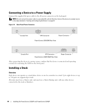
Back-Panel Power Connector Console Port RPS Connector Power Connector PowerConnect 3524/3548 Rear View Console Port EPS Connector PowerConnect 3524P/3548P Rear View Power Connector After connecting the device to the stack as a stand-alone device or can be a member in ...and operating correctly by examining the LEDs on page 47. Installing a Stack Overview Each device can operate as Members. 44 Installing the PowerConnect 3524/P and PowerConnect 3548/P Connect the device to the AC power connector on the back panel. Connecting a Device to a Power Supply Connect the supplied ...
Back-Panel Power Connector Console Port RPS Connector Power Connector PowerConnect 3524/3548 Rear View Console Port EPS Connector PowerConnect 3524P/3548P Rear View Power Connector After connecting the device to the stack as a stand-alone device or can be a member in ...and operating correctly by examining the LEDs on page 47. Installing a Stack Overview Each device can operate as Members. 44 Installing the PowerConnect 3524/P and PowerConnect 3548/P Connect the device to the AC power connector on the back panel. Connecting a Device to a Power Supply Connect the supplied ...
User's Guide
Page 92
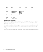
... Power over Ethernet (PoE) provides power to devices over Ethernet removes the necessity of placing network devices next to the PowerConnect device via either all PowerConnect 3524P's 24 FE ports or all PowerConnect 3548P's 48 FE ports. Power over existing LAN cabling, without updating or modifying the network infrastructure. Powered Devices are connected to.... click System→ General→ Power over Ethernet in the tree view. 92 Configuring System Information Powered devices are devices which receive power from the PowerConnect power supplies, for example IP phones.
... Power over Ethernet (PoE) provides power to devices over Ethernet removes the necessity of placing network devices next to the PowerConnect device via either all PowerConnect 3524P's 24 FE ports or all PowerConnect 3548P's 48 FE ports. Power over existing LAN cabling, without updating or modifying the network infrastructure. Powered Devices are connected to.... click System→ General→ Power over Ethernet in the tree view. 92 Configuring System Information Powered devices are devices which receive power from the PowerConnect power supplies, for example IP phones.
Getting Started Guide
Page 11
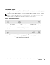
... connect the power cable to the device serial port connector. Back-Panel Power Connector Console Port RPS Connector Power Connector PowerConnect 3524/3548 Rear View Console Port EPS Connector Power Connector PowerConnect 3524P/3548P Rear View Installation 9 You have to connect the device to a power source in the steps detailed in Starting and Configuring...
... connect the power cable to the device serial port connector. Back-Panel Power Connector Console Port RPS Connector Power Connector PowerConnect 3524/3548 Rear View Console Port EPS Connector Power Connector PowerConnect 3524P/3548P Rear View Installation 9 You have to connect the device to a power source in the steps detailed in Starting and Configuring...

Getting Started Guide
Page 241
2007 Dell Inc Dell Inc. PowerEdge ,Dell OpenManage ,Dell OptiPlex ,Dimension ,Dell Precision ,Inspiron ,DELL DellNet ,Axim ,PowerVault ,PowerApp ,PowerConnectוכ Latitude Microsoft .Dell Inc.ו Windows Dell Inc A01 3548P ,3548 ,3524P ,3524 FG745 2007
2007 Dell Inc Dell Inc. PowerEdge ,Dell OpenManage ,Dell OptiPlex ,Dimension ,Dell Precision ,Inspiron ,DELL DellNet ,Axim ,PowerVault ,PowerApp ,PowerConnectוכ Latitude Microsoft .Dell Inc.ו Windows Dell Inc A01 3548P ,3548 ,3524P ,3524 FG745 2007


