
Command Line Interface Guide
Page 29
... using the CLI, perform the following commands to www.microsoft.com for Ryan, is connected to the device prior to the device console port or via a Telnet connection, ensure that Windows® 2000 Service Pack 2 or later is managed by entering command keywords and...managed over cable to the RS-232 serial port of the device to service definitions. c Under Properties, select VT100 for Function, Arrow, and Ctrl keys. Go to begin the configuration procedure: Console> enable Console# configure Console(config)# Using the CLI 29 For more information, see Dell™ PowerConnect™ ...
... using the CLI, perform the following commands to www.microsoft.com for Ryan, is connected to the device prior to the device console port or via a Telnet connection, ensure that Windows® 2000 Service Pack 2 or later is managed by entering command keywords and...managed over cable to the RS-232 serial port of the device to service definitions. c Under Properties, select VT100 for Function, Arrow, and Ctrl keys. Go to begin the configuration procedure: Console> enable Console# configure Console(config)# Using the CLI 29 For more information, see Dell™ PowerConnect™ ...

Command Line Interface Guide
Page 168
...control auto. Syntax • mdix {on - Use the no mdix • on | auto} • no form of this command to disable cable crossover. Indicates auto-negotiation • on port 1/e5. Manual mdix • auto - Example The following example enables flow control on - flowcontrol ...command configures flow control on a given interface. Enables flow control. • off - Automatic mdi/mdix 168 Ethernet Configuration Commands Console(config)# interface ethernet 1/e5 Console(config-if)# flowcontrol on mdix The mdix Interface Configuration (Ethernet) mode command enables...
...control auto. Syntax • mdix {on - Use the no mdix • on | auto} • no form of this command to disable cable crossover. Indicates auto-negotiation • on port 1/e5. Manual mdix • auto - Example The following example enables flow control on - flowcontrol ...command configures flow control on a given interface. Enables flow control. • off - Automatic mdi/mdix 168 Ethernet Configuration Commands Console(config)# interface ethernet 1/e5 Console(config-if)# flowcontrol on mdix The mdix Interface Configuration (Ethernet) mode command enables...
Command Line Interface Guide
Page 169
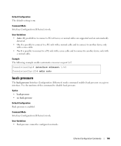
... On: It is possible to connect to a PC only with a normal cable and to connect to another device only with a cross cable and to connect to disable back pressure. Console(config)# interface ethernet 1/e5 Console(config-if)# mdix auto back-pressure The back-pressure Interface Configuration (Ethernet) mode... port 1/e5. Syntax • back-pressure • no form of this command to another device only with a cross cable. • No: It is possible to connect to a PC only with a normal cable. Example The following example enables automatic crossover on . Ethernet Configuration Commands 169
... On: It is possible to connect to a PC only with a normal cable and to connect to another device only with a cross cable and to connect to disable back pressure. Console(config)# interface ethernet 1/e5 Console(config-if)# mdix auto back-pressure The back-pressure Interface Configuration (Ethernet) mode... port 1/e5. Syntax • back-pressure • no form of this command to another device only with a cross cable. • No: It is possible to connect to a PC only with a normal cable. Example The following example enables automatic crossover on . Ethernet Configuration Commands 169

Command Line Interface Guide
Page 277
... test, unless it is a combination port with fiber port active. • The maximum length of a copper cable attached to port 1/e3. Command Mode Privileged EXEC mode. Console# test copper-port tdr 1/e3 Cable is 120 meter. Examples The following example results in a report on fiber ports PHY Diagnostics Commands 277 Syntax... The test copper-port tdr Privileged EXEC mode command uses Time Domain Reflectometry (TDR) technology to diagnose the quality and characteristics of the cable for the TDR test is open at 64 meters Console# test copper-port tdr 2/e3 Can't perform this test on the...
... test, unless it is a combination port with fiber port active. • The maximum length of a copper cable attached to port 1/e3. Command Mode Privileged EXEC mode. Console# test copper-port tdr 1/e3 Cable is 120 meter. Examples The following example results in a report on fiber ports PHY Diagnostics Commands 277 Syntax... The test copper-port tdr Privileged EXEC mode command uses Time Domain Reflectometry (TDR) technology to diagnose the quality and characteristics of the cable for the TDR test is open at 64 meters Console# test copper-port tdr 2/e3 Can't perform this test on the...

Command Line Interface Guide
Page 278
...TDR test is 120 meter. A valid Ethernet port. (Full syntax: unit/port) Default Configuration This command has no default configuration. show copper-ports cable-length The show copper-ports tdr Port ---1/e1 1/e2 1/e3 1/e4 1/e5 Result Length [meters] ------- -------- A valid Ethernet port. (Full syntax... command displays information on the last Time Domain Reflectometry (TDR) test performed on all copper ports. Console> show copper-ports cable-length User EXEC mode command displays the estimated copper cable length attached to a port. Date ----- 13:32:00 23 July 2005 13:32:00 23...
...TDR test is 120 meter. A valid Ethernet port. (Full syntax: unit/port) Default Configuration This command has no default configuration. show copper-ports cable-length The show copper-ports tdr Port ---1/e1 1/e2 1/e3 1/e4 1/e5 Result Length [meters] ------- -------- A valid Ethernet port. (Full syntax... command displays information on the last Time Domain Reflectometry (TDR) test performed on all copper ports. Console> show copper-ports cable-length User EXEC mode command displays the estimated copper cable length attached to a port. Date ----- 13:32:00 23 July 2005 13:32:00 23...

Command Line Interface Guide
Page 279
Console> show copper-ports cable-length Port ---1/e1 1/e2 1/e3 1/g1 Length [meters 50 Copper not active 110-140 Fiber PHY Diagnostics Commands 279 Example The following example displays the estimated copper cable length attached to all ports. User Guidelines The port must be active and working in 100M or 1000M mode. Default Configuration This command has no default configuration. Command Mode User EXEC mode.
Console> show copper-ports cable-length Port ---1/e1 1/e2 1/e3 1/g1 Length [meters 50 Copper not active 110-140 Fiber PHY Diagnostics Commands 279 Example The following example displays the estimated copper cable length attached to all ports. User Guidelines The port must be active and working in 100M or 1000M mode. Default Configuration This command has no default configuration. Command Mode User EXEC mode.

User's Guide
Page 40
... and accessories for damage. The RPS connector is on a secure and clean surface. 4 Remove all cables from the bottom up. 40 Installing the PowerConnect 3524/P and PowerConnect 3548/P • Rack-mount kit for rack installation or wall mounting kit • Documentation CD •... Product Information Guide Unpacking the Device NOTE: Before unpacking the device, inspect the package and immediately report any damage immediately. The Console ...
... and accessories for damage. The RPS connector is on a secure and clean surface. 4 Remove all cables from the bottom up. 40 Installing the PowerConnect 3524/P and PowerConnect 3548/P • Rack-mount kit for rack installation or wall mounting kit • Documentation CD •... Product Information Guide Unpacking the Device NOTE: Before unpacking the device, inspect the package and immediately report any damage immediately. The Console ...
User's Guide
Page 44
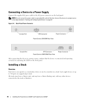
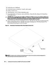
... a grounded AC outlet at this time. NOTE: Do not connect the power cable to the AC power connector on the back panel. Back-Panel Power Connector Console Port RPS Connector Power Connector PowerConnect 3524/3548 Rear View Console Port EPS Connector PowerConnect 3524P/3548P Rear View Power Connector After connecting the device to 384 ports are... by examining the LEDs on page 47. Connect the device to the stack as a stand-alone device or can operate as Members. 44 Installing the PowerConnect 3524/P and PowerConnect 3548/P
... a grounded AC outlet at this time. NOTE: Do not connect the power cable to the AC power connector on the back panel. Back-Panel Power Connector Console Port RPS Connector Power Connector PowerConnect 3524/3548 Rear View Console Port EPS Connector PowerConnect 3524P/3548P Rear View Power Connector After connecting the device to 384 ports are... by examining the LEDs on page 47. Connect the device to the stack as a stand-alone device or can operate as Members. 44 Installing the PowerConnect 3524/P and PowerConnect 3548/P
User's Guide
Page 46
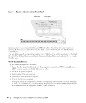
... seconds. The unit ID is connected to a VT100 terminal device or VT100 terminal emulator via the RS-232 crossover cable. 2 Locate an AC power receptacle. 3 Deactivate the AC power receptacle. 4 Connect the device to the AC ...ID LEDs. If the device is a stand-alone unit, the Stack LED is illuminated. 46 Installing the PowerConnect 3524/P and PowerConnect 3548/P Unit ID 1 and 2 are reserved for the Master and Backup Master unit, and unit ID 3... unit ID that the stand-alone/Master device Console port is manually configured by using the Stack ID button. The LED flashes for Member units.
... seconds. The unit ID is connected to a VT100 terminal device or VT100 terminal emulator via the RS-232 crossover cable. 2 Locate an AC power receptacle. 3 Deactivate the AC power receptacle. 4 Connect the device to the AC ...ID LEDs. If the device is a stand-alone unit, the Stack LED is illuminated. 46 Installing the PowerConnect 3524/P and PowerConnect 3548/P Unit ID 1 and 2 are reserved for the Master and Backup Master unit, and unit ID 3... unit ID that the stand-alone/Master device Console port is manually configured by using the Stack ID button. The LED flashes for Member units.
User's Guide
Page 47
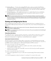
...terminal desktop system running VT100 terminal emulation software • An RS-232 crossover cable with a female DB-9 connector for the Console port and the appropriate connector for each unit. Installing the PowerConnect 3524/P and PowerConnect 3548/P 47 Unit 1 and Unit 2 are selected. Starting and Configuring the Device...ID button. When LED 8 is a male DB-9 connector, implemented as a stand-alone. Performing the steps one unit at support.dell.com. See "Stacking Overview" on page 45 before powering up and their Stack IDs are master-enabled units. Pressing the Stack ID ...
...terminal desktop system running VT100 terminal emulation software • An RS-232 crossover cable with a female DB-9 connector for the Console port and the appropriate connector for each unit. Installing the PowerConnect 3524/P and PowerConnect 3548/P 47 Unit 1 and Unit 2 are selected. Starting and Configuring the Device...ID button. When LED 8 is a male DB-9 connector, implemented as a stand-alone. Performing the steps one unit at support.dell.com. See "Stacking Overview" on page 45 before powering up and their Stack IDs are master-enabled units. Pressing the Stack ID ...
User's Guide
Page 48
... Terminal Back Panel NOTE: A console can be connected to the Console port on any unit in HyperTerminal's VT100 emulation. Go to www.microsoft.com for information on Windows 2000 service packs. 8 Connect the female connector of the RS-232 crossover cable directly to none. 6 Under Properties...174; 2000,ensure that the setting is performed only from the stack master (unit ID 1 or 2). 48 Installing the PowerConnect 3524/P and PowerConnect 3548/P Ensure that you have Windows 2000 Service Pack 2 or later installed. The PowerConnect 35xx Series Systems Console port is on the rear panel.
... Terminal Back Panel NOTE: A console can be connected to the Console port on any unit in HyperTerminal's VT100 emulation. Go to www.microsoft.com for information on Windows 2000 service packs. 8 Connect the female connector of the RS-232 crossover cable directly to none. 6 Under Properties...174; 2000,ensure that the setting is performed only from the stack master (unit ID 1 or 2). 48 Installing the PowerConnect 3524/P and PowerConnect 3548/P Ensure that you have Windows 2000 Service Pack 2 or later installed. The PowerConnect 35xx Series Systems Console port is on the rear panel.

User's Guide
Page 167
... VCT tests. tdr interface show copper-port Displays the estimated copper cable length attached to perform tests on SFPs that support the digital diagnostic standard SFF-872. Console# show copper-port cable-length Port Length (meters) ---- 1/e3 110-140 1/e4 Fiber... Viewing Optical Transceiver Diagnostics Use the Optical Transceiver Diagnostics page to a cable-length port. Finisar transceivers do not support transmitter...
... VCT tests. tdr interface show copper-port Displays the estimated copper cable length attached to perform tests on SFPs that support the digital diagnostic standard SFF-872. Console# show copper-port cable-length Port Length (meters) ---- 1/e3 110-140 1/e4 Fiber... Viewing Optical Transceiver Diagnostics Use the Optical Transceiver Diagnostics page to a cable-length port. Finisar transceivers do not support transmitter...

User's Guide
Page 169
... Using CLI Commands The following table contains the CLI command for which the cable is an example of the CLI command: Console# show fiber-ports opticaltransceiver [interface] [detailed] Description Displays the optical transceiver diagnostics. The following field: • Unit No. - Table 6-32. Figure 6-54. Warning, E - The unit ...
... Using CLI Commands The following table contains the CLI command for which the cable is an example of the CLI command: Console# show fiber-ports opticaltransceiver [interface] [detailed] Description Displays the optical transceiver diagnostics. The following field: • Unit No. - Table 6-32. Figure 6-54. Warning, E - The unit ...

User's Guide
Page 471
...66 B Back panels, 35 Backup master, 12 BootP, 454 BPDU, 327, 344, 454 Bridge Protocol Data Unit, 454 Broadcast, 102, 104 Buttons, 72 C Cables, 165, 167 CBC, 219 CIDR, 455 Cipher Block-Chaining, 219 CLI, 12, 24 Command Line Interface, 12, 24 Command Mode Overview, 74 Communities, 234 ...Configuration file, 248 Console, 116 CoS, 445 Critical, 114, 116 D Debug, 114, 116 Default Gateway, 129-130 Default Gateway, IPv6, 142 Default settings, 256 Defining device information,...
...66 B Back panels, 35 Backup master, 12 BootP, 454 BPDU, 327, 344, 454 Bridge Protocol Data Unit, 454 Broadcast, 102, 104 Buttons, 72 C Cables, 165, 167 CBC, 219 CIDR, 455 Cipher Block-Chaining, 219 CLI, 12, 24 Command Line Interface, 12, 24 Command Mode Overview, 74 Communities, 234 ...Configuration file, 248 Console, 116 CoS, 445 Critical, 114, 116 D Debug, 114, 116 Default Gateway, 129-130 Default Gateway, IPv6, 142 Default settings, 256 Defining device information,...

Getting Started Guide
Page 8
... the device from the box and place it on a secure and clean surface. 4 Remove all cables from the bottom up. 1 Place the supplied rack-mounting bracket on one side of the device,...the device line up to the mounting holes on the back panel of the devices. The Console port is on the rack-mounting bracket. CAUTION: When mounting multiple devices into a rack... Extended Power Supply (EPS) is optional, but recommended. The following mounting instructions apply to the PowerConnect 3500 Series switches. Unpacking Package Contents While unpacking the device, ensure that connect to or support ...
... the device from the box and place it on a secure and clean surface. 4 Remove all cables from the bottom up. 1 Place the supplied rack-mounting bracket on one side of the device,...the device line up to the mounting holes on the back panel of the devices. The Console port is on the rack-mounting bracket. CAUTION: When mounting multiple devices into a rack... Extended Power Supply (EPS) is optional, but recommended. The following mounting instructions apply to the PowerConnect 3500 Series switches. Unpacking Package Contents While unpacking the device, ensure that connect to or support ...
Getting Started Guide
Page 11
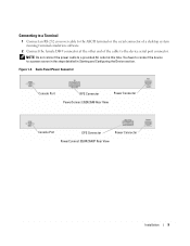
... terminal emulation software. 2 Connect the female DB-9 connector at this time. Back-Panel Power Connector Console Port RPS Connector Power Connector PowerConnect 3524/3548 Rear View Console Port EPS Connector Power Connector PowerConnect 3524P/3548P Rear View Installation 9 Figure 1-3. NOTE: Do not connect the power cable to a grounded AC outlet at the other end of the...
... terminal emulation software. 2 Connect the female DB-9 connector at this time. Back-Panel Power Connector Console Port RPS Connector Power Connector PowerConnect 3524/3548 Rear View Console Port EPS Connector Power Connector PowerConnect 3524P/3548P Rear View Installation 9 Figure 1-3. NOTE: Do not connect the power cable to a grounded AC outlet at the other end of the...

Getting Started Guide
Page 16
... and Unit 2 are selected. To power up the device perform the following tasks: a Ensure that the device is as per the "Stacking Cable Diagram" before powering up the devices. 14 Stacking c Deactivate the AC power receptacle. The unit ID selection process is connected to a VT100 ...the appropriate Stack ID LED is illuminated. 2 Selection process - When powering up the device - f Confirm that the stand-alone/Master device Console port is completed when the 15-second selection period expires. During this period, you can select a specific Stack ID by examining the LEDs on...
... and Unit 2 are selected. To power up the device perform the following tasks: a Ensure that the device is as per the "Stacking Cable Diagram" before powering up the devices. 14 Stacking c Deactivate the AC power receptacle. The unit ID selection process is connected to a VT100 ...the appropriate Stack ID LED is illuminated. 2 Selection process - When powering up the device - f Confirm that the stand-alone/Master device Console port is completed when the 15-second selection period expires. During this period, you can select a specific Stack ID by examining the LEDs on...

Getting Started Guide
Page 17
...-232 crossover cable with a female DB-9 connector for the Console port and the appropriate connector for the terminal To connect a terminal to the device Console port, perform the following is part of a stack, only one device called the Master unit in the Dell PowerConnect 3500 Series ...User's Guide on the front panel of the user documentation from the Dell Support website at support.dell.com. Connecting the Terminal to a terminal desktop system running VT100 terminal emulation software. The Console port connector is a male DB...
...-232 crossover cable with a female DB-9 connector for the Console port and the appropriate connector for the terminal To connect a terminal to the device Console port, perform the following is part of a stack, only one device called the Master unit in the Dell PowerConnect 3500 Series ...User's Guide on the front panel of the user documentation from the Dell Support website at support.dell.com. Connecting the Terminal to a terminal desktop system running VT100 terminal emulation software. The Console port connector is a male DB...
Getting Started Guide
Page 18
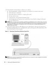
... 2000, Windows XP, or Widows Viste service packs. 3 Connect the female connector of the RS-232 crossover cable directly to the console. The PowerConnect 3500 Series Console port is on the Master unit/stand-alone device, and tighten the captive retaining screws. b Set the data...rate to 8 data bits, 1 stop bit, and no parity. Connecting to PowerConnect 3500 series Console Port Terminal PowerConnect Rear Panel NOTE: You can connect a console to none. Figure 3-1. d Set flow control to the Console port on any unit in HyperTerminal's VT100 emulation. 2 Ensure that the terminal ...
... 2000, Windows XP, or Widows Viste service packs. 3 Connect the female connector of the RS-232 crossover cable directly to the console. The PowerConnect 3500 Series Console port is on the Master unit/stand-alone device, and tighten the captive retaining screws. b Set the data...rate to 8 data bits, 1 stop bit, and no parity. Connecting to PowerConnect 3500 series Console Port Terminal PowerConnect Rear Panel NOTE: You can connect a console to none. Figure 3-1. d Set flow control to the Console port on any unit in HyperTerminal's VT100 emulation. 2 Ensure that the terminal ...


