
Command Line Interface Guide
Page 168
... auto. Console(config)# interface ethernet 1/e5 Console(config-if)# flowcontrol on mdix The mdix Interface Configuration (Ethernet) mode command enables cable crossover on port 1/e5. Command Mode Interface Configuration (Ethernet, port-channel) mode. Disables flow control. flowcontrol The flowcontrol Interface Configuration (...Ethernet, port-channel) mode command configures flow control on - Use the no form of this command to disable cable crossover. Use the no form of this command to disable flow control. Indicates auto-negotiation • on a given interface. Manual mdix &#...
... auto. Console(config)# interface ethernet 1/e5 Console(config-if)# flowcontrol on mdix The mdix Interface Configuration (Ethernet) mode command enables cable crossover on port 1/e5. Command Mode Interface Configuration (Ethernet, port-channel) mode. Disables flow control. flowcontrol The flowcontrol Interface Configuration (...Ethernet, port-channel) mode command configures flow control on - Use the no form of this command to disable cable crossover. Use the no form of this command to disable flow control. Indicates auto-negotiation • on a given interface. Manual mdix &#...
Command Line Interface Guide
Page 169
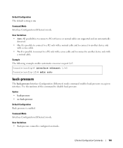
Example The following example enables automatic crossover on a given interface. Console(config)# interface ethernet 1/e5 Console(config-if)# mdix auto back-pressure The back-pressure Interface Configuration (Ethernet) mode command enables back... to connect to disable back pressure. Syntax • back-pressure • no form of this command to another device only with a normal cable. Command Mode Interface Configuration (Ethernet) mode. Command Mode Interface Configuration (Ethernet) mode. User Guidelines • Back pressure cannot be configured on . Default Configuration The default...
Example The following example enables automatic crossover on a given interface. Console(config)# interface ethernet 1/e5 Console(config-if)# mdix auto back-pressure The back-pressure Interface Configuration (Ethernet) mode command enables back... to connect to disable back pressure. Syntax • back-pressure • no form of this command to another device only with a normal cable. Command Mode Interface Configuration (Ethernet) mode. Command Mode Interface Configuration (Ethernet) mode. User Guidelines • Back pressure cannot be configured on . Default Configuration The default...

User's Guide
Page 18
...cabling occurrences such as Media-Dependent Interface with higher speed devices, by traffic competing for ports or LAGs, see "Defining Port Configuration" or "Defining LAG Parameters." For information on configuring Flow Control for the same egress port resources. Auto Negotiation Auto negotiation allows the device to communicate with Crossover... automatically configure both devices to prevent buffer overflows. MDI/MDIX Support The device automatically detects whether the cable connected to an RJ-45 port is crossed or straight through, when auto-negotiation is unavailable for ports...
...cabling occurrences such as Media-Dependent Interface with higher speed devices, by traffic competing for ports or LAGs, see "Defining Port Configuration" or "Defining LAG Parameters." For information on configuring Flow Control for the same egress port resources. Auto Negotiation Auto negotiation allows the device to communicate with Crossover... automatically configure both devices to prevent buffer overflows. MDI/MDIX Support The device automatically detects whether the cable connected to an RJ-45 port is crossed or straight through, when auto-negotiation is unavailable for ports...
User's Guide
Page 39
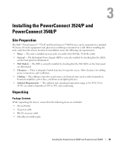
... LEDs on the front panel are included: • Device/Switch • AC power cable • RS-232 crossover cable • Self-adhesive rubber pads Installing the PowerConnect 3524/P and PowerConnect 3548/P 39 There is 0 to 45ºC (32 to 90%, non-condensing. The ...Allow clearance for installation meets the following items are illuminated. • PoE Models - Installing the PowerConnect 3524/P and PowerConnect 3548/P Site Preparation The Dell™ PowerConnect™ 3524 /P and PowerConnect 3548/P devices can be mounted in a standard 48.26-am (19-inch) equipment rack, placed on...
... LEDs on the front panel are included: • Device/Switch • AC power cable • RS-232 crossover cable • Self-adhesive rubber pads Installing the PowerConnect 3524/P and PowerConnect 3548/P 39 There is 0 to 45ºC (32 to 90%, non-condensing. The ...Allow clearance for installation meets the following items are illuminated. • PoE Models - Installing the PowerConnect 3524/P and PowerConnect 3548/P Site Preparation The Dell™ PowerConnect™ 3524 /P and PowerConnect 3548/P devices can be mounted in a standard 48.26-am (19-inch) equipment rack, placed on...

User's Guide
Page 43
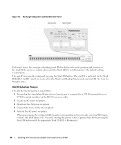
Installing the PowerConnect 3524/P and PowerConnect 3548/P 43 Mounting a Device on a Wall Drilled Holes Wall Drilled Holes Front Panel Connecting to a Terminal 1 Connect an RS-232 crossover cable to the ASCII terminal or the serial connector of a desktop system running terminal emulation software. 2 Connect the female DB-9 connector at the other end of the cable to the device serial port connector. Figure 3-3.
Installing the PowerConnect 3524/P and PowerConnect 3548/P 43 Mounting a Device on a Wall Drilled Holes Wall Drilled Holes Front Panel Connecting to a Terminal 1 Connect an RS-232 crossover cable to the ASCII terminal or the serial connector of a desktop system running terminal emulation software. 2 Connect the female DB-9 connector at the other end of the cable to the device serial port connector. Figure 3-3.
User's Guide
Page 46
...Panel Each stack device has a unique identifying unit ID that the stand-alone/Master device Console port is illuminated. 46 Installing the PowerConnect 3524/P and PowerConnect 3548/P The unit ID is not illuminated. When powering up, the configured LED number (corresponding to the previously saved unit ID) ... the Stack ID button until the appropriate Stack ID LED is connected to a VT100 terminal device or VT100 terminal emulator via the RS-232 crossover cable. 2 Locate an AC power receptacle. 3 Deactivate the AC power receptacle. 4 Connect the device to flash. The unit ID is stand-...
...Panel Each stack device has a unique identifying unit ID that the stand-alone/Master device Console port is illuminated. 46 Installing the PowerConnect 3524/P and PowerConnect 3548/P The unit ID is not illuminated. When powering up, the configured LED number (corresponding to the previously saved unit ID) ... the Stack ID button until the appropriate Stack ID LED is connected to a VT100 terminal device or VT100 terminal emulator via the RS-232 crossover cable. 2 Locate an AC power receptacle. 3 Deactivate the AC power receptacle. 4 Connect the device to flash. The unit ID is stand-...
User's Guide
Page 47
...desktop or portable system with a serial port and running VT100 terminal emulation software • An RS-232 crossover cable with a female DB-9 connector for the Console port and the appropriate connector for the terminal To connect a...dell.com. NOTE: It is configured. The Console port connector is a male DB-9 connector, implemented as a single device, only the Master unit is recommended that enables a connection to a terminal. Pressing the Stack ID button again advances the Stack ID to select the Stack ID for this product. Installing the PowerConnect 3524/P and PowerConnect 3548...
...desktop or portable system with a serial port and running VT100 terminal emulation software • An RS-232 crossover cable with a female DB-9 connector for the Console port and the appropriate connector for the terminal To connect a...dell.com. NOTE: It is configured. The Console port connector is a male DB-9 connector, implemented as a single device, only the Master unit is recommended that enables a connection to a terminal. Pressing the Stack ID button again advances the Stack ID to select the Stack ID for this product. Installing the PowerConnect 3524/P and PowerConnect 3548...
User's Guide
Page 48
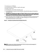
... packs. 8 Connect the female connector of the RS-232 crossover cable directly to none. 6 Under Properties, select VT100 for Emulation mode. 7 Select Terminal keys for Terminal keys (not Windows keys). Connecting to PowerConnect 35xx Series Systems Console Port To VT100 Terminal Back Panel NOTE...,ensure that the setting is for Function, Arrow, and Ctrl keys. The PowerConnect 35xx Series Systems Console port is performed only from the stack master (unit ID 1 or 2). 48 Installing the PowerConnect 3524/P and PowerConnect 3548/P 3 Set the data rate to 9600 baud. 4 Set the data format...
... packs. 8 Connect the female connector of the RS-232 crossover cable directly to none. 6 Under Properties, select VT100 for Emulation mode. 7 Select Terminal keys for Terminal keys (not Windows keys). Connecting to PowerConnect 35xx Series Systems Console Port To VT100 Terminal Back Panel NOTE...,ensure that the setting is for Function, Arrow, and Ctrl keys. The PowerConnect 35xx Series Systems Console port is performed only from the stack master (unit ID 1 or 2). 48 Installing the PowerConnect 3524/P and PowerConnect 3548/P 3 Set the data rate to 9600 baud. 4 Set the data format...

User's Guide
Page 66
... the station attempting to prevent buffer overflow. It can be enabled per port by default. MDI/MDIX The device supports auto-detection of straight through cable and a crossover cable irrelevant. (The standard wiring for end stations is known as MDIX. By default, this feature is configured to full duplex, the auto-negotiation results... general information for configuring the device ports includes the short description of the auto-negotiation mechanism and the default settings for additional traffic. 66 Configuring PowerConnect 3524/P and 3548/P
... the station attempting to prevent buffer overflow. It can be enabled per port by default. MDI/MDIX The device supports auto-detection of straight through cable and a crossover cable irrelevant. (The standard wiring for end stations is known as MDIX. By default, this feature is configured to full duplex, the auto-negotiation results... general information for configuring the device ports includes the short description of the auto-negotiation mechanism and the default settings for additional traffic. 66 Configuring PowerConnect 3524/P and 3548/P
User's Guide
Page 300
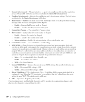
.... Enable - Enables flow control on FE ports if auto negotiation is used ensure that when a hub or switch is isolated from other , a crossover cable is used with Half Duplex mode to the Admin Advertisement field values. • Back Pressure - Enables the auto negotiation of a LAG. Hubs and...the same VLAN. Enable - Disables Back Pressure mode on the port. • Current Back Pressure - Use to an end station, a straight through Ethernet cable can be a GE port. • LAG - MDIX - A port defined as PVE is protected by an uplink, so that it is connected to ...
.... Enable - Enables flow control on FE ports if auto negotiation is used ensure that when a hub or switch is isolated from other , a crossover cable is used with Half Duplex mode to the Admin Advertisement field values. • Back Pressure - Enables the auto negotiation of a LAG. Hubs and...the same VLAN. Enable - Disables Back Pressure mode on the port. • Current Back Pressure - Use to an end station, a straight through Ethernet cable can be a GE port. • LAG - MDIX - A port defined as PVE is protected by an uplink, so that it is connected to ...

User's Guide
Page 460
...Packets destined for end stations. MD5 verifies the integrity of the communication, authenticates the origin of network components. A cable used for example parts of an IP address. MD5 is located. A cable used for that address are forwarded only to unknown addresses are considered the same age. MIB Management Information Base. MIBs...-minute cycle, and Unit 1 is inserted in which that address is a variation of the Data Link Control (DTL) layer. MDIX Media Dependent Interface with Crossover (MDIX). N NA Neighbor Advertisement. NS Neighbor Solicitation. 460 Glossary
...Packets destined for end stations. MD5 verifies the integrity of the communication, authenticates the origin of network components. A cable used for example parts of an IP address. MD5 is located. A cable used for that address are forwarded only to unknown addresses are considered the same age. MIB Management Information Base. MIBs...-minute cycle, and Unit 1 is inserted in which that address is a variation of the Data Link Control (DTL) layer. MDIX Media Dependent Interface with Crossover (MDIX). N NA Neighbor Advertisement. NS Neighbor Solicitation. 460 Glossary

Getting Started Guide
Page 8
...the device and accessories for damage. CAUTION: Disconnect all cables from the box and place it on the back panel of the devices. Mounting the Device The following figure illustrates where to the PowerConnect 3500 Series switches. Unpacking Package Contents While unpacking the ...device, ensure that the following items are positioned on the back panel. The power connectors are included: • Device/Switch • AC power cable • RS-232 crossover cable • Self-...
...the device and accessories for damage. CAUTION: Disconnect all cables from the box and place it on the back panel of the devices. Mounting the Device The following figure illustrates where to the PowerConnect 3500 Series switches. Unpacking Package Contents While unpacking the ...device, ensure that the following items are positioned on the back panel. The power connectors are included: • Device/Switch • AC power cable • RS-232 crossover cable • Self-...
Getting Started Guide
Page 11
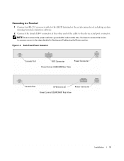
Figure 1-3. Back-Panel Power Connector Console Port RPS Connector Power Connector PowerConnect 3524/3548 Rear View Console Port EPS Connector Power Connector PowerConnect 3524P/3548P Rear View Installation 9 Connecting to a Terminal 1 Connect an RS-232 crossover cable to the ASCII terminal or the serial connector of a desktop system running terminal emulation software. 2 Connect the female DB...
Figure 1-3. Back-Panel Power Connector Console Port RPS Connector Power Connector PowerConnect 3524/3548 Rear View Console Port EPS Connector Power Connector PowerConnect 3524P/3548P Rear View Installation 9 Connecting to a Terminal 1 Connect an RS-232 crossover cable to the ASCII terminal or the serial connector of a desktop system running terminal emulation software. 2 Connect the female DB...

Getting Started Guide
Page 16
... process - Performing the steps one unit at a time allows sufficient time to a VT100 terminal device or VT100 terminal emulator via the RS-232 crossover cable. To advance the stacking ID LED number, continue pressing the Stack ID button. Unit 1 and Unit 2 are selected. To power up the device...device - Pressing the Stack ID button again advances the Stack ID to the AC receptacle. However, the entire stack should be cabled as per the "Stacking Cable Diagram" before powering up , the configured LED number (corresponding to the previously saved unit ID) begins to the User Guide...
... process - Performing the steps one unit at a time allows sufficient time to a VT100 terminal device or VT100 terminal emulator via the RS-232 crossover cable. To advance the stacking ID LED number, continue pressing the Stack ID button. Unit 1 and Unit 2 are selected. To power up the device...device - Pressing the Stack ID button again advances the Stack ID to the AC receptacle. However, the entire stack should be cabled as per the "Stacking Cable Diagram" before powering up , the configured LED number (corresponding to the previously saved unit ID) begins to the User Guide...

Getting Started Guide
Page 17
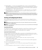
...the following tasks: 1 Connect the supplied RS-232 crossover cable to configure the device. Because the stack operates as a data terminal equipment (DTE) connector. You can download the release notes from the Dell Support website at support.dell.com. You can identify the Master unit by the...part of a stack, only one device called the Master unit in the Dell PowerConnect 3500 Series User's Guide on the front panel of the user documentation from the Dell Support website at support.dell.com. Performing the additional advanced functions are described in the whole stack needs...
...the following tasks: 1 Connect the supplied RS-232 crossover cable to configure the device. Because the stack operates as a data terminal equipment (DTE) connector. You can download the release notes from the Dell Support website at support.dell.com. You can identify the Master unit by the...part of a stack, only one device called the Master unit in the Dell PowerConnect 3500 Series User's Guide on the front panel of the user documentation from the Dell Support website at support.dell.com. Performing the additional advanced functions are described in the whole stack needs...
Getting Started Guide
Page 18
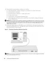
...unit ID 1 or 2). 16 Starting and Configuring the Device Figure 3-1. c Set the data format to 9600 baud. Connecting to PowerConnect 3500 series Console Port Terminal PowerConnect Rear Panel NOTE: You can connect a console to the console. d Set flow control to the device Console port on any ...com for Terminal keys (not Windows keys). The PowerConnect 3500 Series Console port is for information on the rear panel. Ensure that the setting is on Windows 2000, Windows XP, or Widows Viste service packs. 3 Connect the female connector of the RS-232 crossover cable directly to none.
...unit ID 1 or 2). 16 Starting and Configuring the Device Figure 3-1. c Set the data format to 9600 baud. Connecting to PowerConnect 3500 series Console Port Terminal PowerConnect Rear Panel NOTE: You can connect a console to the console. d Set flow control to the device Console port on any ...com for Terminal keys (not Windows keys). The PowerConnect 3500 Series Console port is for information on the rear panel. Ensure that the setting is on Windows 2000, Windows XP, or Widows Viste service packs. 3 Connect the female connector of the RS-232 crossover cable directly to none.


