User's Guide (.htm)
Page 3
Contents 1 Introduction System Description 21 PowerConnect 3424 21 PowerConnect 3424P 21 PowerConnect 3448 22 PowerConnect 3448P 22 Stacking Overview 22 Understanding the Stack Topology 23 Stacking Failover Topology 23 Stacking Members and Unit ID 23 Removing and Replacing Stacking Members 24 ...
Contents 1 Introduction System Description 21 PowerConnect 3424 21 PowerConnect 3424P 21 PowerConnect 3448 22 PowerConnect 3448P 22 Stacking Overview 22 Understanding the Stack Topology 23 Stacking Failover Topology 23 Stacking Members and Unit ID 23 Removing and Replacing Stacking Members 24 ...
User's Guide (.htm)
Page 4
... Definitions 40 Gigabit Port LEDs 43 System LEDs 44 Power Supplies 45 Stack ID Button 47 Reset Button 47 Ventilation System 47 3 Installing the PowerConnect 3424/P and PowerConnect 3448/P Site Preparation 49 Unpacking 49 Package Contents 49 Unpacking the Device 50 Mounting the Device 50 Installing in a Rack 50 Installing on a Flat Surface...
... Definitions 40 Gigabit Port LEDs 43 System LEDs 44 Power Supplies 45 Stack ID Button 47 Reset Button 47 Ventilation System 47 3 Installing the PowerConnect 3424/P and PowerConnect 3448/P Site Preparation 49 Unpacking 49 Package Contents 49 Unpacking the Device 50 Mounting the Device 50 Installing in a Rack 50 Installing on a Flat Surface...
User's Guide (.htm)
Page 10
...PowerConnect 3424 and PowerConnect 3424P . . . 21 PowerConnect 3448 and PowerConnect 3448P . . . 22 Stacking Ring Topology 23 PowerConnect 3448/P replaces PowerConnect 3448/P 26 PowerConect 3424/P port replaces PowerConnect 3448/P port 26 PowerConnect 3448/P port replaces PowerConect 3424/P Port 27 PowerConnect 3424 Front Panel 37 PowerConnect 3424 Back Panel 38 PowerConnect 3448 Front Panel 38 PowerConnect 3448...Diagram 55 Stacking Configuration and Identification Panel . . . 56 Connecting to PowerConnect 3400 Series Console Port 58 10 Contents Figure 2-1. Figure 3-3. Figure 1-6....
...PowerConnect 3424 and PowerConnect 3424P . . . 21 PowerConnect 3448 and PowerConnect 3448P . . . 22 Stacking Ring Topology 23 PowerConnect 3448/P replaces PowerConnect 3448/P 26 PowerConect 3424/P port replaces PowerConnect 3448/P port 26 PowerConnect 3448/P port replaces PowerConect 3424/P Port 27 PowerConnect 3424 Front Panel 37 PowerConnect 3424 Back Panel 38 PowerConnect 3448 Front Panel 38 PowerConnect 3448...Diagram 55 Stacking Configuration and Identification Panel . . . 56 Connecting to PowerConnect 3400 Series Console Port 58 10 Contents Figure 2-1. Figure 3-3. Figure 1-6....
User's Guide (.htm)
Page 16
... 371 Global Settings 375 Interface Settings 377 CoS to Queue 379 DSCP to Queue 380 PowerConnect 3424 and PowerConnect 3448 RJ-45 100BaseT LED Indications 41 PowerConnect 3424P and PowerConnect 3448P RJ-45 Copper based 100BaseT LED Indications 42 PowerConnect 3424 and PowerConnect 3448 RJ-45 Copper based 100BaseT LED Indications 43 SFP Port LED Indications 43 System LED...
... 371 Global Settings 375 Interface Settings 377 CoS to Queue 379 DSCP to Queue 380 PowerConnect 3424 and PowerConnect 3448 RJ-45 100BaseT LED Indications 41 PowerConnect 3424P and PowerConnect 3448P RJ-45 Copper based 100BaseT LED Indications 42 PowerConnect 3424 and PowerConnect 3448 RJ-45 Copper based 100BaseT LED Indications 43 SFP Port LED Indications 43 System LED...
User's Guide (.htm)
Page 21
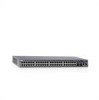
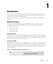
... versatility with up to forward traffic in a stand-alone device, or as a stand-alone device. The PowerConnect 3424 and 3448 series include the following device types: • PowerConnect 3424 • PowerConnect 3424P • PowerConnect 3448 • PowerConnect 3448P PowerConnect 3424 The PowerConnect 3424 provides 24 10/100Mbps ports plus two SFP ports, and two Copper ports which can be used...
... versatility with up to forward traffic in a stand-alone device, or as a stand-alone device. The PowerConnect 3424 and 3448 series include the following device types: • PowerConnect 3424 • PowerConnect 3424P • PowerConnect 3448 • PowerConnect 3448P PowerConnect 3424 The PowerConnect 3424 provides 24 10/100Mbps ports plus two SFP ports, and two Copper ports which can be used...
User's Guide (.htm)
Page 22
... Master detects and reconfigures the ports with minimal operational impact in stand-alone mode, or as the Backup Master. In addition, PowerConnect 3448P provides PoE. www.dell.com | support.dell.com PowerConnect 3448 The PowerConnect 3448 provides 48 10/100Mbps ports plus two SFP ports, and two Copper ports which the stack is downloaded separately for each stack...
... Master detects and reconfigures the ports with minimal operational impact in stand-alone mode, or as the Backup Master. In addition, PowerConnect 3448P provides PoE. www.dell.com | support.dell.com PowerConnect 3448 The PowerConnect 3448 provides 48 10/100Mbps ports plus two SFP ports, and two Copper ports which the stack is downloaded separately for each stack...
User's Guide (.htm)
Page 23
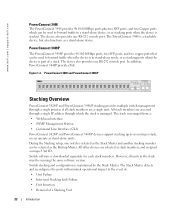
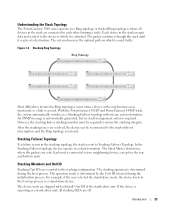
... but no stack management action is determined during the initialization process. The device units are sent. Introduction 23 With the PowerConnect 3424/P and PowerConnect 3448/P stack, the system automatically switches to the stack without any system downtime. However, the stacking link or stacking member ... to each other forming a circle. A stacked Ring topology is operating as a stand-alone device. Understanding the Stack Topology The PowerConnect 3400 series operates in the boot-up process as a stand-alone unit, all devices in the stack are connected to Stacking Failover...
... but no stack management action is determined during the initialization process. The device units are sent. Introduction 23 With the PowerConnect 3424/P and PowerConnect 3448/P stack, the system automatically switches to the stack without any system downtime. However, the stacking link or stacking member ... to each other forming a circle. A stacked Ring topology is operating as a stand-alone device. Understanding the Stack Topology The PowerConnect 3400 series operates in the boot-up process as a stand-alone unit, all devices in the stack are connected to Stacking Failover...
User's Guide (.htm)
Page 25
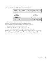
... Switch Administrator home page, and can be configured through the CLI or SNMP interfaces. For example, • If a PowerConnect 3424/P replaces PowerConnect 3424/P, all port configurations remain the same. • If a PowerConnect 3448/P replaces the PowerConnect 3448/P, all units in the Master unit is applied to the inserted stack member. If a unit attempts to boot without...
... Switch Administrator home page, and can be configured through the CLI or SNMP interfaces. For example, • If a PowerConnect 3424/P replaces PowerConnect 3424/P, all port configurations remain the same. • If a PowerConnect 3448/P replaces the PowerConnect 3448/P, all units in the Master unit is applied to the inserted stack member. If a unit attempts to boot without...
User's Guide (.htm)
Page 27
Introduction 27 The running on the Backup Master. Any dynamic tables are relearned if a failure occurs. PowerConnect 3448/P port replaces PowerConect 3424/P Port Same Configuration Same Configuration Switching from the Stack Master to the Backup Stack Master The Backup Master replaces the Stack ...
Introduction 27 The running on the Backup Master. Any dynamic tables are relearned if a failure occurs. PowerConnect 3448/P port replaces PowerConect 3424/P Port Same Configuration Same Configuration Switching from the Stack Master to the Backup Stack Master The Backup Master replaces the Stack ...
User's Guide (.htm)
Page 38
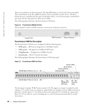
...following ports: • 48 FE ports - The following figure illustrates the PowerConnect 3448 front panel. The upper row of ports is the Reset Button which are two buttons on the front panel. Ports G3- www.dell.com | support.dell.com There are copper ports. RS-232 Console based port The following ... numbers 2-48. RJ-45 ports designated as stacking ports, or used to manually reset the device. Console Port RPS Connector Power Connector PowerConnect 3448 Port Description The PowerConnect 3448 device is used to select the unit number. The Stack ID button is prevented.
...following ports: • 48 FE ports - The following figure illustrates the PowerConnect 3448 front panel. The upper row of ports is the Reset Button which are two buttons on the front panel. Ports G3- www.dell.com | support.dell.com There are copper ports. RS-232 Console based port The following ... numbers 2-48. RJ-45 ports designated as stacking ports, or used to manually reset the device. Console Port RPS Connector Power Connector PowerConnect 3448 Port Description The PowerConnect 3448 device is used to select the unit number. The Stack ID button is prevented.
User's Guide (.htm)
Page 39
...for communication via a Complex Programmable Logic Device (CPLD) which is used to manually reset the device. Console Port Hardware Description 39 PowerConnect 3448 Back Panel Console Port RPS Connector Power Connector The back panel contains an RPS connector, console port and power connector. The default .... SFP Ports The Small Form Factor Plugable (SFP) ports are all the device LEDs. Figure 2-5. The following figure illustrates the PowerConnect 3448 back panel: Figure 2-4. The baud rate can be configured from 2400 bps up to select the unit number. There are two ...
...for communication via a Complex Programmable Logic Device (CPLD) which is used to manually reset the device. Console Port Hardware Description 39 PowerConnect 3448 Back Panel Console Port RPS Connector Power Connector The back panel contains an RPS connector, console port and power connector. The default .... SFP Ports The Small Form Factor Plugable (SFP) ports are all the device LEDs. Figure 2-5. The following figure illustrates the PowerConnect 3448 back panel: Figure 2-4. The baud rate can be configured from 2400 bps up to select the unit number. There are two ...
User's Guide (.htm)
Page 40
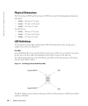
...the left side of links, power supplies, fans, and system diagnostics. www.dell.com | support.dell.com Physical Dimensions The PowerConnect 3424/P and PowerConnect 3448/P devices have the following figure illustrates the 10/100 Base-T port LEDs on The PowerConnect 3424 /P and PowerConnect 3448/P switches: Figure 2-6. RJ-45 Copper Based 10/100 BaseT LEDs Speed/... contains light emitting diodes (LED) that indicate the status of the port, while the link/duplex/activity LED is located on the PowerConnect 3424 /P and PowerConnect 3448/P has two LEDs marked as LNK/ACT. 40 Hardware Description
...the left side of links, power supplies, fans, and system diagnostics. www.dell.com | support.dell.com Physical Dimensions The PowerConnect 3424/P and PowerConnect 3448/P devices have the following figure illustrates the 10/100 Base-T port LEDs on The PowerConnect 3424 /P and PowerConnect 3448/P switches: Figure 2-6. RJ-45 Copper Based 10/100 BaseT LEDs Speed/... contains light emitting diodes (LED) that indicate the status of the port, while the link/duplex/activity LED is located on the PowerConnect 3424 /P and PowerConnect 3448/P has two LEDs marked as LNK/ACT. 40 Hardware Description
User's Guide (.htm)
Page 41
.... The port is either transmitting or receiving data at 10 Mbs. The port is running at 10 Mbps. The following table: Table 2-1. PowerConnect 3424 and PowerConnect 3448 RJ-45 100BaseT LED Indications LED Link/Activity/Speed FDX Color Green Static Green Flashing Yellow Static Yellow Flashing OFF Green Static OFF Description...Half Duplex mode, Hardware Description 41 The port is currently not operating. RJ-45 1000 BaseT LED The RJ-45 LED indications for PowerConnect 3424 and PowerConnect 3448 are described in the following figure illustrates the 100 Base-T LEDs. Figure 2-7.
.... The port is either transmitting or receiving data at 10 Mbs. The port is running at 10 Mbps. The following table: Table 2-1. PowerConnect 3424 and PowerConnect 3448 RJ-45 100BaseT LED Indications LED Link/Activity/Speed FDX Color Green Static Green Flashing Yellow Static Yellow Flashing OFF Green Static OFF Description...Half Duplex mode, Hardware Description 41 The port is currently not operating. RJ-45 1000 BaseT LED The RJ-45 LED indications for PowerConnect 3424 and PowerConnect 3448 are described in the following figure illustrates the 100 Base-T LEDs. Figure 2-7.
User's Guide (.htm)
Page 43
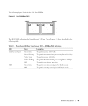
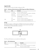
On the PowerConnect 3424/P and PowerConnect 3448/P devices, the LEDs are located between ports and are described in shape. SFP Port LEDs The SFP port LED indications are round in the following ... on each have one LED marked as LNK/ACT. OFF The port is running at 10 or 100Mbs. The port is currently not linked. PowerConnect 3424 and PowerConnect 3448 RJ-45 Copper based 100BaseT LED Indications LED Link/Activity/Speed Color Green Static Green Flashing Yellow Static Yellow Flashing FDX OFF Green Static...
On the PowerConnect 3424/P and PowerConnect 3448/P devices, the LEDs are located between ports and are described in shape. SFP Port LEDs The SFP port LED indications are round in the following ... on each have one LED marked as LNK/ACT. OFF The port is running at 10 or 100Mbs. The port is currently not linked. PowerConnect 3424 and PowerConnect 3448 RJ-45 Copper based 100BaseT LED Indications LED Link/Activity/Speed Color Green Static Green Flashing Yellow Static Yellow Flashing FDX OFF Green Static...
User's Guide (.htm)
Page 44
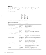
... the permitted temperature range. Red Static One or more of The PowerConnect 3424 /P and PowerConnect 3448/P devices provide information about the power supplies, fans, thermal conditions, and diagnostics. www.dell.com | support.dell.com System LEDs The system LEDs of the device fans is currently...is turned on. System LED Indicators LED Power Supply (PWR) Redundant Power Supply (RPS) (models: 3424 and 3448 ) Redundant Power Supply (RPS) (models: 3424P and 3448P ) Diagnostics (DIAG) Temperature (TEMP) Fan (FAN) Color Green Static OFF Green Static Description The switch is currently...
... the permitted temperature range. Red Static One or more of The PowerConnect 3424 /P and PowerConnect 3448/P devices provide information about the power supplies, fans, thermal conditions, and diagnostics. www.dell.com | support.dell.com System LEDs The system LEDs of the device fans is currently...is turned on. System LED Indicators LED Power Supply (PWR) Redundant Power Supply (RPS) (models: 3424 and 3448 ) Redundant Power Supply (RPS) (models: 3424P and 3448P ) Diagnostics (DIAG) Temperature (TEMP) Fan (FAN) Color Green Static OFF Green Static Description The switch is currently...
User's Guide (.htm)
Page 45
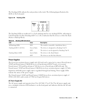
...LEDs are numbered 1- 6. The device is regulated through load sharing. The PowerConnect 3424/P and PowerConnect 3448/P devices have an internal power supply of the power supply. The PowerConnect 3424/P and PowerConnect 3448/P devices have an internal power supply (12 Volt). LED indicator is ...device has an internal power supply unit (AC unit) and a connector to connect PowerConnect 3424/P and PowerConnect 3448/P devices to a PowerConnect EPS-470 unit, or to connect PowerConnect 3424 and PowerConnect 3448 devices to 63 Hz. The Stacking LEDs indicate the unit position in the stack...
...LEDs are numbered 1- 6. The device is regulated through load sharing. The PowerConnect 3424/P and PowerConnect 3448/P devices have an internal power supply of the power supply. The PowerConnect 3424/P and PowerConnect 3448/P devices have an internal power supply (12 Volt). LED indicator is ...device has an internal power supply unit (AC unit) and a connector to connect PowerConnect 3424/P and PowerConnect 3448/P devices to a PowerConnect EPS-470 unit, or to connect PowerConnect 3424 and PowerConnect 3448 devices to 63 Hz. The Stacking LEDs indicate the unit position in the stack...
User's Guide (.htm)
Page 46
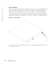
The PowerConnect 3424/P and PowerConnect 3448/P switches connect to an external EPS-470 unit to provide a redundant power option. The front panel "RPS" LED indicates whether the external RPS-600 is ..., the probability of failure in the event of a power outage decreases. 46 Hardware Description See Table 2-5 for RPS LED definition. No configuration is required. www.dell.com | support.dell.com DC Power Supply Unit The PowerConnect 3424 and PowerConnect 3448 switches connect to an external RPS-600 unit to provide a redundant power option.
The PowerConnect 3424/P and PowerConnect 3448/P switches connect to an external EPS-470 unit to provide a redundant power option. The front panel "RPS" LED indicates whether the external RPS-600 is ..., the probability of failure in the event of a power outage decreases. 46 Hardware Description See Table 2-5 for RPS LED definition. No configuration is required. www.dell.com | support.dell.com DC Power Supply Unit The PowerConnect 3424 and PowerConnect 3448 switches connect to an external RPS-600 unit to provide a redundant power option.
User's Guide (.htm)
Page 47
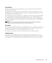
...(3-6). If a Unit ID has already been selected, press the Stack ID button several times until no stacking LED is reset. The non-PoE PowerConnect 3424 and PowerConnect 3448 devices have two built-in a stack, the Master unit is either 1 or 2, the backup Master is either 1 or 2 depending on ... The Stack Master receives the Unit ID of booting the device. If only a member unit is booted in fans. Ventilation System The PowerConnect 3424/P and PowerConnect 3448/P switches with the PoE feature have a reset button, located on the Unit ID of the switch is activated by observing the LED ...
...(3-6). If a Unit ID has already been selected, press the Stack ID button several times until no stacking LED is reset. The non-PoE PowerConnect 3424 and PowerConnect 3448 devices have two built-in a stack, the Master unit is either 1 or 2, the backup Master is either 1 or 2 depending on ... The Stack Master receives the Unit ID of booting the device. If only a member unit is booted in fans. Ventilation System The PowerConnect 3424/P and PowerConnect 3448/P switches with the PoE feature have a reset button, located on the Unit ID of the switch is activated by observing the LED ...
User's Guide (.htm)
Page 49
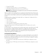
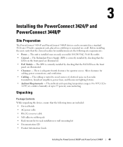
.... • PoE Models - There is installed near an easily accessible 100-240 VAC, 50-60 Hz outlet. • General - Installing the PowerConnect 3424/P and PowerConnect 3448/P Site Preparation The PowerConnect 3424 /P and PowerConnect 3448/P devices can be mounted in a standard 48.26-am (19-inch) equipment rack, placed on a tabletop or mounted on the front panel... • Self-adhesive rubber pads • Rack-mount kit for rack installation or wall mounting kit • Documentation CD • Product Information Guide Installing the PowerConnect 3424/P and PowerConnect 3448/P 49
.... • PoE Models - There is installed near an easily accessible 100-240 VAC, 50-60 Hz outlet. • General - Installing the PowerConnect 3424/P and PowerConnect 3448/P Site Preparation The PowerConnect 3424 /P and PowerConnect 3448/P devices can be mounted in a standard 48.26-am (19-inch) equipment rack, placed on a tabletop or mounted on the front panel... • Self-adhesive rubber pads • Rack-mount kit for rack installation or wall mounting kit • Documentation CD • Product Information Guide Installing the PowerConnect 3424/P and PowerConnect 3448/P 49
User's Guide (.htm)
Page 50
...CAUTION: Disconnect all packing material. 5 Inspect the device and accessories for safety information on devices connected to The PowerConnect 3424/P and PowerConnect 3448/P devices. The Console port is recommended. Mounting the Device The following mounting instructions apply to or that support the...4 Remove all cables from the bottom up. 50 Installing the PowerConnect 3424/P and PowerConnect 3448/P Installing in a Rack CAUTION: Read the Safety Information included in a rack or cabinet. www.dell.com | support.dell.com Unpacking the Device NOTE: Before unpacking the device, inspect ...
...CAUTION: Disconnect all packing material. 5 Inspect the device and accessories for safety information on devices connected to The PowerConnect 3424/P and PowerConnect 3448/P devices. The Console port is recommended. Mounting the Device The following mounting instructions apply to or that support the...4 Remove all cables from the bottom up. 50 Installing the PowerConnect 3424/P and PowerConnect 3448/P Installing in a Rack CAUTION: Read the Safety Information included in a rack or cabinet. www.dell.com | support.dell.com Unpacking the Device NOTE: Before unpacking the device, inspect ...


