Setup and Features Information Tech Sheet
Page 6
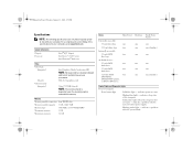
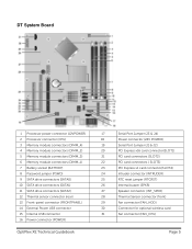
... 19, 2010 4:39 PM Specifications NOTE: The following specifications are only those required by computers shipped with Intel i7 and Intel i5 quad-core processors. System Information Chipset Processor Intel® Q57 chipset Intel Core™ i3/i5/i7 series Intel Pentium® dual-core Video Video type: Integrated Discrete Video memory...
... 19, 2010 4:39 PM Specifications NOTE: The following specifications are only those required by computers shipped with Intel i7 and Intel i5 quad-core processors. System Information Chipset Processor Intel® Q57 chipset Intel Core™ i3/i5/i7 series Intel Pentium® dual-core Video Video type: Integrated Discrete Video memory...
Technical Guidebook
Page 2
... System Board Small Form Factor Computer (SFF) View Small Form Factor Back Panel Connectors Small Form Factor System Board MARKETING SYSTEM CONFIGURATIONS Operating System, Chipset Processor, Advanced System Manageability Modes, System Monitoring Options Memory Drives and Removable Storage System Board Connectors, Graphics/Video Controller External Ports/Connectors Communications-Integrated LAN, Wireless... 3 4 5 6 7 8 9 10 11 12-13 13 14 15 16 17 18 19 20 21 22-24 24-26 26-32 33-34 35 36 37-38 OptiPlex XE Technical Guidebook Page 2
... System Board Small Form Factor Computer (SFF) View Small Form Factor Back Panel Connectors Small Form Factor System Board MARKETING SYSTEM CONFIGURATIONS Operating System, Chipset Processor, Advanced System Manageability Modes, System Monitoring Options Memory Drives and Removable Storage System Board Connectors, Graphics/Video Controller External Ports/Connectors Communications-Integrated LAN, Wireless... 3 4 5 6 7 8 9 10 11 12-13 13 14 15 16 17 18 19 20 21 22-24 24-26 26-32 33-34 35 36 37-38 OptiPlex XE Technical Guidebook Page 2
Technical Guidebook
Page 5
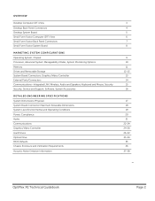
DT System Board 1 Processor power connector (12VPOWER) 2 Processor connector (CPU) 3 Memory module connectors (DIMM_4) 4 Memory module connectors (DIMM_2) 5 Memory module connectors (DIMM_3) 6 Memory module connectors (DIMM_1) 7 Battery socket (BATTERY) 8 Password jumper (PSWD)... (SATA2) 12 Thermal sensor connector (rear) 13 Front-panel connector (FRONTPANEL) 14 External Power USB connector 15 Internal USB connector 16 Power connector (POWER) OptiPlex XE Technical Guidebook 17 Serial Port Jumper (J3 & J4) 18 Power connector (24V POWER) 19 Serial Port Jumper (J1 & J2) 20 PCI Express ...
DT System Board 1 Processor power connector (12VPOWER) 2 Processor connector (CPU) 3 Memory module connectors (DIMM_4) 4 Memory module connectors (DIMM_2) 5 Memory module connectors (DIMM_3) 6 Memory module connectors (DIMM_1) 7 Battery socket (BATTERY) 8 Password jumper (PSWD)... (SATA2) 12 Thermal sensor connector (rear) 13 Front-panel connector (FRONTPANEL) 14 External Power USB connector 15 Internal USB connector 16 Power connector (POWER) OptiPlex XE Technical Guidebook 17 Serial Port Jumper (J3 & J4) 18 Power connector (24V POWER) 19 Serial Port Jumper (J1 & J2) 20 PCI Express ...
Technical Guidebook
Page 8
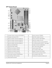
... (FAN_HDD) 26 Speaker connector (INT_SPKR) 27 Thermal Sensor connector (front) 28 Fan connector (FAN_CPU) 29 Connector for optional wireless card OptiPlex XE Technical Guidebook Page 8 SFF System Board 1 Processor power connector (12VPOWER) 2 Processor connector (CPU) 3 Memory module connectors (DIMM_4) 4 Memory module connectors (DIMM_2) 5 Memory module connectors (DIMM_3) 6 Memory module connectors (DIMM_1) 7 Battery socket...
... (FAN_HDD) 26 Speaker connector (INT_SPKR) 27 Thermal Sensor connector (front) 28 Fan connector (FAN_CPU) 29 Connector for optional wireless card OptiPlex XE Technical Guidebook Page 8 SFF System Board 1 Processor power connector (12VPOWER) 2 Processor connector (CPU) 3 Memory module connectors (DIMM_4) 4 Memory module connectors (DIMM_2) 5 Memory module connectors (DIMM_3) 6 Memory module connectors (DIMM_1) 7 Battery socket...
Technical Guidebook
Page 10
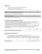
... the power or O/S state of the system. DT SFF Dell Watchdog Timer Optional via factory installation only OptiPlex XE Technical Guidebook Page 10 Processor NOTES: • The OptiPlex XE uses CPUs from Intel's long lifecycle Embedded Roadmap • Processor numbers are not a measure of performance. • Processor availability subject to change and may vary by region...
... the power or O/S state of the system. DT SFF Dell Watchdog Timer Optional via factory installation only OptiPlex XE Technical Guidebook Page 10 Processor NOTES: • The OptiPlex XE uses CPUs from Intel's long lifecycle Embedded Roadmap • Processor numbers are not a measure of performance. • Processor availability subject to change and may vary by region...
Technical Guidebook
Page 11
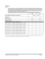
... of available memory will continue to the operating system is available to 64-bit operating systems. • Memory modules should be used by computer memory; OptiPlex XE Technical Guidebook Page 11 Any address space reserved for these components cannot be installed in matched pairs, the computer will be less than 4GB... 2GB DIMMs; Moreover, certain components within the computer require address space in performance. To fully utilize 4GB or more of memory requires a 64-bit enabled processor and 64-bit operating system.
... of available memory will continue to the operating system is available to 64-bit operating systems. • Memory modules should be used by computer memory; OptiPlex XE Technical Guidebook Page 11 Any address space reserved for these components cannot be installed in matched pairs, the computer will be less than 4GB... 2GB DIMMs; Moreover, certain components within the computer require address space in performance. To fully utilize 4GB or more of memory requires a 64-bit enabled processor and 64-bit operating system.
Technical Guidebook
Page 13
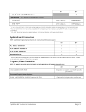
... functionality. Graphics/Video Controller NOTE: DT supports low profile card or full height card with specific processors Enhanced Graphic/Video Options 512MB AMD RADEON HD4550 Graphics, DP, DVI Optional full height or low profile card OptiPlex XE Technical Guidebook Page 13 using DVD+R media provides maximum compatibility. 4 DVD-ROM drives may not...
... functionality. Graphics/Video Controller NOTE: DT supports low profile card or full height card with specific processors Enhanced Graphic/Video Options 512MB AMD RADEON HD4550 Graphics, DP, DVI Optional full height or low profile card OptiPlex XE Technical Guidebook Page 13 using DVD+R media provides maximum compatibility. 4 DVD-ROM drives may not...
Technical Guidebook
Page 35
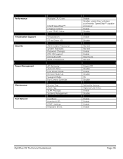
... Enable Enable Deactivate Not set Power Off Disable Enable Disable S3 Disable Set by the factory Optional User Entry Enable Disable Enable Enable Enable Enable OptiPlex XE Technical Guidebook Page 35 Performance Virtualization Support Security Power Management Maintenance Post Behavior Multiple CPU Core: Intel® SpeedStep™: C States Control: Limit CPUID...: Service Tag: Asset Tag: SERR Message: Systems Management Fast Boot: Numlock LED: POST HotKeys: Keyboard Errors: Enable Disable, unless the customer purchased a SpeedStep™ capable processor.
... Enable Enable Deactivate Not set Power Off Disable Enable Disable S3 Disable Set by the factory Optional User Entry Enable Disable Enable Enable Enable Enable OptiPlex XE Technical Guidebook Page 35 Performance Virtualization Support Security Power Management Maintenance Post Behavior Multiple CPU Core: Intel® SpeedStep™: C States Control: Limit CPUID...: Service Tag: Asset Tag: SERR Message: Systems Management Fast Boot: Numlock LED: POST HotKeys: Keyboard Errors: Enable Disable, unless the customer purchased a SpeedStep™ capable processor.
Service Manual
Page 2
...not covered by performing the removal procedure in this type of the computer. Back to Contents Page Working on Your Computer Dell™ OptiPlex™ 980 Service Manual-Mini-Tower Before Working Inside Your Computer Recommended Tools Turning Off Your Computer After Working Inside Your Computer Before...before you disconnect a cable, pull on its connector or on its edges, not by periodically touching an unpainted metal surface, such as a processor by its pull-tab, not on the back of cable, press in your warranty. Turn off your computer. Unless otherwise noted, each ...
...not covered by performing the removal procedure in this type of the computer. Back to Contents Page Working on Your Computer Dell™ OptiPlex™ 980 Service Manual-Mini-Tower Before Working Inside Your Computer Recommended Tools Turning Off Your Computer After Working Inside Your Computer Before...before you disconnect a cable, pull on its connector or on its edges, not by periodically touching an unpainted metal surface, such as a processor by its pull-tab, not on the back of cable, press in your warranty. Turn off your computer. Unless otherwise noted, each ...

Service Manual
Page 4
...Connectors Cards Physical Drives Environmental External Connectors NOTE: Offerings may vary by computers shipped with Intel i7 and Intel i5 quad-core processors. For more information regarding the configuration of your computer. NOTE: Unless otherwise stated, the specifications are identical for mini-tower,... desktop, and small form factor computers. PCI Express x16 slot supports a PCI Express card Processor Type Quad-Core Dual-Core Level 2 (L2) cache Intel Core i7 series Intel Core i5 series Intel Core i5 series Intel ...
...Connectors Cards Physical Drives Environmental External Connectors NOTE: Offerings may vary by computers shipped with Intel i7 and Intel i5 quad-core processors. For more information regarding the configuration of your computer. NOTE: Unless otherwise stated, the specifications are identical for mini-tower,... desktop, and small form factor computers. PCI Express x16 slot supports a PCI Express card Processor Type Quad-Core Dual-Core Level 2 (L2) cache Intel Core i7 series Intel Core i5 series Intel Core i5 series Intel ...
Service Manual
Page 7
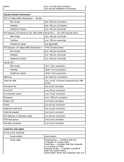
... 7-pin connectors Memory four 240-pin connectors Internal USB one 10-pin connector (supports two USB ports) Processor fan one 5-pin connector Front I/O one 26-pin connector Front panel control one 14-pin connector Processor one 1156-pin connector Power 12V one 4-pin connector Power one 24-pin connector Internal serial card...
... 7-pin connectors Memory four 240-pin connectors Internal USB one 10-pin connector (supports two USB ports) Processor fan one 5-pin connector Front I/O one 26-pin connector Front panel control one 14-pin connector Processor one 1156-pin connector Power 12V one 4-pin connector Power one 24-pin connector Internal serial card...

Service Manual
Page 11
Back to Contents Page Removing and Replacing Parts Dell™ OptiPlex™ 980 Service Manual-Mini-Tower Cover Drive Cover Optical Drive Hard Drive/Cage Front Panel Expansion Card Wireless Module Processor Fan Heat Sink and Processor Memory Module Internal Speaker Front Thermal Sensor Power Supply Control Panel Front I/O Panel Intrusion Switch Coin-Cell Battery System Board Back to Contents Page
Back to Contents Page Removing and Replacing Parts Dell™ OptiPlex™ 980 Service Manual-Mini-Tower Cover Drive Cover Optical Drive Hard Drive/Cage Front Panel Expansion Card Wireless Module Processor Fan Heat Sink and Processor Memory Module Internal Speaker Front Thermal Sensor Power Supply Control Panel Front I/O Panel Intrusion Switch Coin-Cell Battery System Board Back to Contents Page
Service Manual
Page 14
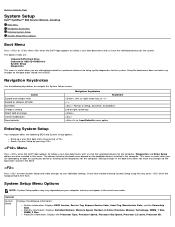
...-arrow key, or +/- < > -Remain in the boot menu does not make changes to user-definable settings. Processor information: Displays the Processor Type, Processor Speed, Processor Bus Speed, Processor L2 cache, Processor ID, Back to Contents Page System Setup Dell™ OptiPlex™ 980 Service Manual-Desktop Boot Menu Navigation Keystrokes Entering System Setup System Setup Menu Options Boot Menu...
...-arrow key, or +/- < > -Remain in the boot menu does not make changes to user-definable settings. Processor information: Displays the Processor Type, Processor Speed, Processor Bus Speed, Processor L2 cache, Processor ID, Back to Contents Page System Setup Dell™ OptiPlex™ 980 Service Manual-Desktop Boot Menu Navigation Keystrokes Entering System Setup System Setup Menu Options Boot Menu...
Service Manual
Page 16
...The TPM Virtualization Technology and Virtualization Technology for Direct Enables or disables the Virtual Machine Monitor (VMM) from adjusting the processor's performance. System Password This option is allowed to use these fields are not active until they are 2 video controller...characters allowed for Direct I /O for additional power saving when idle. Limit CPUID This field limits the maximum value the processor Standard CPUID Function will become the primary video controller when 2 controllers are prevented from utilizing the additional hardware capabilities provided by...
...The TPM Virtualization Technology and Virtualization Technology for Direct Enables or disables the Virtual Machine Monitor (VMM) from adjusting the processor's performance. System Password This option is allowed to use these fields are not active until they are 2 video controller...characters allowed for Direct I /O for additional power saving when idle. Limit CPUID This field limits the maximum value the processor Standard CPUID Function will become the primary video controller when 2 controllers are prevented from utilizing the additional hardware capabilities provided by...
Service Manual
Page 17
... how the system responds when AC power is not set by default. Maintenance Service Tag Asset Tag SERR Messages Displays the Service Tag of the processor. When low power mode is enabled, the integrated network card is disabled when the system is shutdown or in NIC cards will be able to...
... how the system responds when AC power is not set by default. Maintenance Service Tag Asset Tag SERR Messages Displays the Service Tag of the processor. When low power mode is enabled, the integrated network card is disabled when the system is shutdown or in NIC cards will be able to...
Service Manual
Page 24
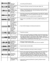
...computer starts normally, continue to install additional memory modules (one . Possible peripheral card or system board failure has occurred. A possible processor failure has occurred. If the computer boots, add the peripheral cards back one by one until you find the bad one at a...Memory modules are detected, but a memory one until you have identified a faulty module or reinstalled all modules without error. Reseat the processor. Reinstall all USB devices and check all peripheral cards from the power supply unit. Power connector not installed properly. A possible system ...
...computer starts normally, continue to install additional memory modules (one . Possible peripheral card or system board failure has occurred. A possible processor failure has occurred. If the computer boots, add the peripheral cards back one by one until you find the bad one at a...Memory modules are detected, but a memory one until you have identified a faulty module or reinstalled all modules without error. Reseat the processor. Reinstall all USB devices and check all peripheral cards from the power supply unit. Power connector not installed properly. A possible system ...
Service Manual
Page 49
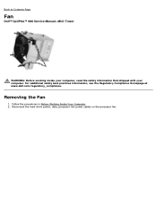
Back to Contents Page Fan Dell™ OptiPlex™ 980 Service Manual-Mini-Tower WARNING: Before working inside your computer, read the safety information that shipped with your computer. Removing the Fan 1. Follow the procedures in Before Working Inside Your Computer. 2. Disconnect the hard-drive power, data, processor-fan power cables on the processor fan. For additional safety best practices information, see the Regulatory Compliance Homepage at www.dell.com/regulatory_compliance.
Back to Contents Page Fan Dell™ OptiPlex™ 980 Service Manual-Mini-Tower WARNING: Before working inside your computer, read the safety information that shipped with your computer. Removing the Fan 1. Follow the procedures in Before Working Inside Your Computer. 2. Disconnect the hard-drive power, data, processor-fan power cables on the processor fan. For additional safety best practices information, see the Regulatory Compliance Homepage at www.dell.com/regulatory_compliance.

Service Manual
Page 50
Remove the screws from the system board. 4. Disconnect the fan connector from the processor fan shroud. 3.
Remove the screws from the system board. 4. Disconnect the fan connector from the processor fan shroud. 3.

Service Manual
Page 51
Replacing the Fan To replace the fan, perform the above steps in reverse order. Remove the processor fan from the heat sink. Back to Contents Page 5.
Replacing the Fan To replace the fan, perform the above steps in reverse order. Remove the processor fan from the heat sink. Back to Contents Page 5.
Service Manual
Page 52
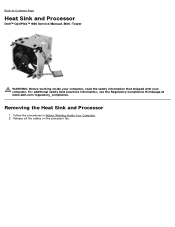
Follow the procedures in Before Working Inside Your Computer. 2. For additional safety best practices information, see the Regulatory Compliance Homepage at www.dell.com/regulatory_compliance. Release all the cables on the processor fan. Back to Contents Page Heat Sink and Processor Dell™ OptiPlex™ 980 Service Manual-Mini-Tower WARNING: Before working inside your computer, read the safety information that shipped with your computer. Removing the Heat Sink and Processor 1.
Follow the procedures in Before Working Inside Your Computer. 2. For additional safety best practices information, see the Regulatory Compliance Homepage at www.dell.com/regulatory_compliance. Release all the cables on the processor fan. Back to Contents Page Heat Sink and Processor Dell™ OptiPlex™ 980 Service Manual-Mini-Tower WARNING: Before working inside your computer, read the safety information that shipped with your computer. Removing the Heat Sink and Processor 1.


