Setup and Features Information Tech Sheet
Page 1
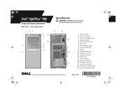
... Form Factor: DCCY1F series February 2010 Y991Mam1.fm Page 1 Tuesday, January 19, 2010 4:39 PM Dell™ OptiPlex™ 980 Setup and Features Information Mini Tower - Front and Back View 1 2 34 12 11 5 19 ...6 7 18 8 9 10 About Warnings WARNING: A WARNING indicates a potential for property damage, personal injury, or death. 13 14 15 16 17 1 drive activity light 2 network activity light 3 Wi-Fi® activity light (optional) 4 diagnostic lights (4) 5 power button, power light...
... Form Factor: DCCY1F series February 2010 Y991Mam1.fm Page 1 Tuesday, January 19, 2010 4:39 PM Dell™ OptiPlex™ 980 Setup and Features Information Mini Tower - Front and Back View 1 2 34 12 11 5 19 ...6 7 18 8 9 10 About Warnings WARNING: A WARNING indicates a potential for property damage, personal injury, or death. 13 14 15 16 17 1 drive activity light 2 network activity light 3 Wi-Fi® activity light (optional) 4 diagnostic lights (4) 5 power button, power light...
Setup and Features Information Tech Sheet
Page 2
... drive 3 optical drive eject button 4 USB 2.0 connectors (2) 5 microphone connector 6 headphone connector 7 flex bay 8 drive activity light 9 network activity light 10 Wi-Fi activity light (optional) 11 diagnostic lights (4) 12 power supply diagnostic button 13 power supply diagnostic light 14 14 padlock ring 15 security cable slot 15 16 power cable connector 17 back panel connectors...
... drive 3 optical drive eject button 4 USB 2.0 connectors (2) 5 microphone connector 6 headphone connector 7 flex bay 8 drive activity light 9 network activity light 10 Wi-Fi activity light (optional) 11 diagnostic lights (4) 12 power supply diagnostic button 13 power supply diagnostic light 14 14 padlock ring 15 security cable slot 15 16 power cable connector 17 back panel connectors...
Setup and Features Information Tech Sheet
Page 3
Y991Mam1.fm Page 3 Tuesday, January 19, 2010 4:39 PM Small Form Factor - Front and Back View 1 11 10 9 8 2 76 3 5 4 18 17 12 13 14 15 16 1 power button, power light 2 optical drive 3 optical drive eject button 4 flex bay 5 headphone connector 6 microphone connector 7 USB 2.0 connectors (2) 8 drive activity light 9 network activity light 10 Wi-Fi activity light (optional) 11 diagnostic lights (4) 12 power supply diagnostic button 13 power supply diagnostic light 14 padlock ring 15 security cable slot 16 power cable connector 17 back panel connectors 18 expansion card slots (2)
Y991Mam1.fm Page 3 Tuesday, January 19, 2010 4:39 PM Small Form Factor - Front and Back View 1 11 10 9 8 2 76 3 5 4 18 17 12 13 14 15 16 1 power button, power light 2 optical drive 3 optical drive eject button 4 flex bay 5 headphone connector 6 microphone connector 7 USB 2.0 connectors (2) 8 drive activity light 9 network activity light 10 Wi-Fi activity light (optional) 11 diagnostic lights (4) 12 power supply diagnostic button 13 power supply diagnostic light 14 padlock ring 15 security cable slot 16 power cable connector 17 back panel connectors 18 expansion card slots (2)
Setup and Features Information Tech Sheet
Page 6
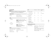
...174; dual-core Video Video type: Integrated Discrete Video memory: Integrated Intel Graphics Media Accelerator HD NOTE: Not supported by law to support.dell.com. Memory Memory module connector Memory module capacity Memory type Minimum memory Maximum memory four DIMM slots 1 GB, 2 GB, 4 GB 1066...RW Combo, or DVD+/-RW drives Small Form Factor one one (slimline) one two one one (slimline) Control Lights and Diagnostic Lights Front of computer Power button light Solid blue light - PCI-E x16 graphics card Upto 1759 MB (shared) NOTE: The memory shared is dependent upon the operating ...
...174; dual-core Video Video type: Integrated Discrete Video memory: Integrated Intel Graphics Media Accelerator HD NOTE: Not supported by law to support.dell.com. Memory Memory module connector Memory module capacity Memory type Minimum memory Maximum memory four DIMM slots 1 GB, 2 GB, 4 GB 1066...RW Combo, or DVD+/-RW drives Small Form Factor one one (slimline) one two one one (slimline) Control Lights and Diagnostic Lights Front of computer Power button light Solid blue light - PCI-E x16 graphics card Upto 1759 MB (shared) NOTE: The memory shared is dependent upon the operating ...
Setup and Features Information Tech Sheet
Page 7
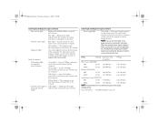
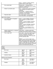
... and is reading data from or writing data to the power connector (at the back of computer Link integrity light on the Dell Support website at support.dell.com/manuals. The power supply is present. AC power must be connected to the drive. Coin-cell battery 3V CR2032 lithium coin cell Back of...
... and is reading data from or writing data to the power connector (at the back of computer Link integrity light on the Dell Support website at support.dell.com/manuals. The power supply is present. AC power must be connected to the drive. Coin-cell battery 3V CR2032 lithium coin cell Back of...
Technical Guidebook
Page 3
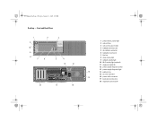
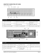
DESKTOP COMPUTER (DT) VIEW Front and Back View FRONT VIEW 1 Drive activity light 4 Network activity light 2 2 Wi-Fi activity light 3 Network activity light 1 5 DVD drive bay 6 USB 2.0 connectors (2) 7 External power button connector 8 Diagnostic Lights (4) 9 Power button, power light BACK VIEW 10 Power supply diagnostic button 11 Power supply diagnostic light 12 Cover release latch 13 Padlock ring 14 Security cable slot 15 Power cable connector 16 Back panel connectors 17 Expansion card slots (4) OptiPlex XE Technical Guidebook Page 3
DESKTOP COMPUTER (DT) VIEW Front and Back View FRONT VIEW 1 Drive activity light 4 Network activity light 2 2 Wi-Fi activity light 3 Network activity light 1 5 DVD drive bay 6 USB 2.0 connectors (2) 7 External power button connector 8 Diagnostic Lights (4) 9 Power button, power light BACK VIEW 10 Power supply diagnostic button 11 Power supply diagnostic light 12 Cover release latch 13 Padlock ring 14 Security cable slot 15 Power cable connector 16 Back panel connectors 17 Expansion card slots (4) OptiPlex XE Technical Guidebook Page 3
Technical Guidebook
Page 4
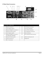
DT Back Panel Connectors BACK PANEL CONNECTORS 1 Serial Connector 1 2 Link Integrity Light 2 3 Network Adapter Connector 2 4 Network Activity Light 2 5 Link Integrity Light 1 6 Network Adapter Connector 1 (TruManage Capability) 7 Network Activity Light 1 8 Serial Connector 2 9 Wi-Fi Connector 10 PS/2 Mouse Connector 11 Line-Out Connector 12 Line-In/Mic Connector 13 PS/2 Keyboard Connector 14 VGA Connector 15 24V Powered USB Connector 16 USB 2.0 Connectors (4) 17 DisplayPort OptiPlex XE Technical Guidebook Page 4
DT Back Panel Connectors BACK PANEL CONNECTORS 1 Serial Connector 1 2 Link Integrity Light 2 3 Network Adapter Connector 2 4 Network Activity Light 2 5 Link Integrity Light 1 6 Network Adapter Connector 1 (TruManage Capability) 7 Network Activity Light 1 8 Serial Connector 2 9 Wi-Fi Connector 10 PS/2 Mouse Connector 11 Line-Out Connector 12 Line-In/Mic Connector 13 PS/2 Keyboard Connector 14 VGA Connector 15 24V Powered USB Connector 16 USB 2.0 Connectors (4) 17 DisplayPort OptiPlex XE Technical Guidebook Page 4
Technical Guidebook
Page 6
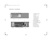
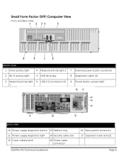
Small Form Factor (SFF) Computer View Front and Back View FRONT VIEW 1 Drive activity light 2 Wi-Fi activity light 4 Network activity light 2 5 DVD drive bay 7 External power button connector 8 Diagnostic Lights (4) 3 Network activity light 6 USB 2.0 connectors (2) 9 Power button, power light 1 BACK VIEW 10 Power supply diagnostic button 13 Padlock ring 11 Power supply diagnostic light 14 Security cable slot 12 Cover release latch 15 Power cable connector OptiPlex XE Technical Guidebook 16 Back panel connectors 17 Expansion card slots (2) Page 6
Small Form Factor (SFF) Computer View Front and Back View FRONT VIEW 1 Drive activity light 2 Wi-Fi activity light 4 Network activity light 2 5 DVD drive bay 7 External power button connector 8 Diagnostic Lights (4) 3 Network activity light 6 USB 2.0 connectors (2) 9 Power button, power light 1 BACK VIEW 10 Power supply diagnostic button 13 Padlock ring 11 Power supply diagnostic light 14 Security cable slot 12 Cover release latch 15 Power cable connector OptiPlex XE Technical Guidebook 16 Back panel connectors 17 Expansion card slots (2) Page 6
Technical Guidebook
Page 7
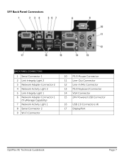
SFF Back Panel Connectors BACK PANEL CONNECTORS 1 Serial Connector 1 2 Link Integrity Light 2 3 Network Adapter Connector 2 4 Network Activity Light 2 5 Link Integrity Light 1 6 Network Adapter Connector 1 (TruManage Capability) 7 Network Activity Light 1 8 Serial Connector 2 9 Wi-Fi Connector 10 PS/2 Mouse Connector 11 Line-Out Connector 12 Line-In/Mic Connector 13 PS/2 Keyboard Connector 14 VGA Connector 15 24V Powered USB Connector 16 USB 2.0 Connectors (4) 17 DisplayPort OptiPlex XE Technical Guidebook Page 7
SFF Back Panel Connectors BACK PANEL CONNECTORS 1 Serial Connector 1 2 Link Integrity Light 2 3 Network Adapter Connector 2 4 Network Activity Light 2 5 Link Integrity Light 1 6 Network Adapter Connector 1 (TruManage Capability) 7 Network Activity Light 1 8 Serial Connector 2 9 Wi-Fi Connector 10 PS/2 Mouse Connector 11 Line-Out Connector 12 Line-In/Mic Connector 13 PS/2 Keyboard Connector 14 VGA Connector 15 24V Powered USB Connector 16 USB 2.0 Connectors (4) 17 DisplayPort OptiPlex XE Technical Guidebook Page 7

Service Manual
Page 4
... information regarding the configuration of your computer, click Start® Help and Support and select the option to Contents Page Technical Specifications Processor Controls and Lights Memory Network Expansion Bus Audio Video Power System Information System Board Connectors Cards Physical Drives Environmental External Connectors NOTE: Offerings may vary by computers shipped...
... information regarding the configuration of your computer, click Start® Help and Support and select the option to Contents Page Technical Specifications Processor Controls and Lights Memory Network Expansion Bus Audio Video Power System Information System Board Connectors Cards Physical Drives Environmental External Connectors NOTE: Offerings may vary by computers shipped...
Service Manual
Page 7
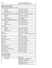
... PCI 2.3 data width (maximum) - 32 bits Mini-tower two 120-pin connectors Desktop two 120-pin connectors Small form factor one 3-pin connector Controls and Lights Front of the computer Power button Power...
... PCI 2.3 data width (maximum) - 32 bits Mini-tower two 120-pin connectors Desktop two 120-pin connectors Small form factor one 3-pin connector Controls and Lights Front of the computer Power button Power...
Service Manual
Page 8
...255 W (nonEPA) 235 W (nonEPA) 1603 BTU/hr (non-EPA) 1341 BTU/hr (non-EPA) Diagnostic lights four amber lights on integrated yellow light - a blinking yellow light network adapter indicates that the computer is functional. the power supply is turned on and is not detecting a physical ...a problem with the system board or power supply. indicates that a good connection exists between the network and the computer. Network connectivity light blue - indicates that the computer is not detecting a physical connection to the hard drive. Back of the computer) and the electrical ...
...255 W (nonEPA) 235 W (nonEPA) 1603 BTU/hr (non-EPA) 1341 BTU/hr (non-EPA) Diagnostic lights four amber lights on integrated yellow light - a blinking yellow light network adapter indicates that the computer is functional. the power supply is turned on and is not detecting a physical ...a problem with the system board or power supply. indicates that a good connection exists between the network and the computer. Network connectivity light blue - indicates that the computer is not detecting a physical connection to the hard drive. Back of the computer) and the electrical ...
Service Manual
Page 14
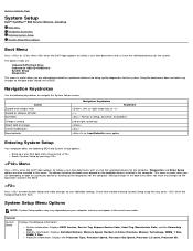
Back to Contents Page System Setup Dell™ OptiPlex™ 980 Service Manual-Desktop Boot Menu Navigation Keystrokes Entering System Setup System Setup Menu Options Boot Menu Press or when the Dell™ logo appears to initiate a one -time boot menu with a list of the valid boot... Setup Menu Options NOTE: System Setup options may vary depending on the bootable devices installed in this key, press when the keyboard lights first flash. Memory information: Displays Installed Memory, Memory Speed, Number of Active Channels, Memory Technology, DIMM_1 Size, DIMM_2 Size. This...
Back to Contents Page System Setup Dell™ OptiPlex™ 980 Service Manual-Desktop Boot Menu Navigation Keystrokes Entering System Setup System Setup Menu Options Boot Menu Press or when the Dell™ logo appears to initiate a one -time boot menu with a list of the valid boot... Setup Menu Options NOTE: System Setup options may vary depending on the bootable devices installed in this key, press when the keyboard lights first flash. Memory information: Displays Installed Memory, Memory Speed, Number of Active Channels, Memory Technology, DIMM_1 Size, DIMM_2 Size. This...
Service Manual
Page 19
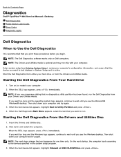
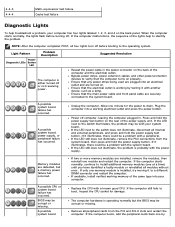
... a message stating that no diagnostics utility partition has been found, run . Back to Contents Page Diagnostics Dell™ OptiPlex™ 980 Service Manual-Desktop Dell Diagnostics Power Button Light Codes Beep Codes Diagnostic Lights Dell Diagnostics When to Use the Dell Diagnostics It is recommended that you print these procedures before you see the Microsoft® Windows®...
... a message stating that no diagnostics utility partition has been found, run . Back to Contents Page Diagnostics Dell™ OptiPlex™ 980 Service Manual-Desktop Dell Diagnostics Power Button Light Codes Beep Codes Diagnostic Lights Dell Diagnostics When to Use the Dell Diagnostics It is recommended that you print these procedures before you see the Microsoft® Windows®...
Service Manual
Page 20
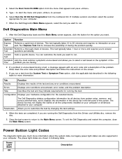
...problem quickly. Help Describes the test and may not display the names of devices. Configuration Displays your Test part. Power Light State Off Description Option Function Express Performs a quick test of all the components installed on your hardware configuration for more ... disc. 5. Write down the error code and problem description and follow the instructions on the symptom of the screen. The Dell Diagnostics obtains configuration information for your computer. Extended Performs a thorough check of the test and any error conditions encountered. Type ...
...problem quickly. Help Describes the test and may not display the names of devices. Configuration Displays your Test part. Power Light State Off Description Option Function Express Performs a quick test of all the components installed on your hardware configuration for more ... disc. 5. Write down the error code and problem description and follow the instructions on the symptom of the screen. The Dell Diagnostics obtains configuration information for your computer. Extended Performs a thorough check of the test and any error conditions encountered. Type ...
Service Manual
Page 21
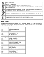
... up . Solid Green System is not yet active. Indicates system has power, but the POWER_GOOD signal is in . Look at the diagnostic lights to indicate it is probable that prevents the computer from completing the boot routine until the indicated condition is in a low power state, either... S1 or S3. Second state of beeps that identifies the problem or that may emit a series of the light at the diagnostic lights for further information. The following table lists the beep codes that can help you identify a faulty component or assembly. Blinking Amber Solid...
... up . Solid Green System is not yet active. Indicates system has power, but the POWER_GOOD signal is in . Look at the diagnostic lights to indicate it is probable that prevents the computer from completing the boot routine until the indicated condition is in a low power state, either... S1 or S3. Second state of beeps that identifies the problem or that may emit a series of the light at the diagnostic lights for further information. The following table lists the beep codes that can help you identify a faulty component or assembly. Blinking Amber Solid...
Service Manual
Page 23
... board failure has occurred. If the LED next to a different DIMM connector and restart the computer. BIOS may be corrupt or missing. Light Pattern Power Diagnostic LEDs Button LED Problem Description The computer is probably with a known good CPU. Press and hold the power supply button....from the system board, then press and hold the power supply test button on the rear of the same type into your computer has four lights labeled 1, 2, 3, and 4 on properly. Bypass power strips, power extension cables, and other power protection devices to drain. The computer...
... board failure has occurred. If the LED next to a different DIMM connector and restart the computer. BIOS may be corrupt or missing. Light Pattern Power Diagnostic LEDs Button LED Problem Description The computer is probably with a known good CPU. Press and hold the power supply button....from the system board, then press and hold the power supply test button on the rear of the same type into your computer has four lights labeled 1, 2, 3, and 4 on properly. Bypass power strips, power extension cables, and other power protection devices to drain. The computer...
Service Manual
Page 24
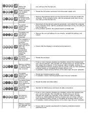
... bad one . Disconnect all power and data cables. If available, install working graphics card into your computer. A possible system board failure has occurred. The diagnostic lights are detected. If the computer boots, add the peripheral cards back one by one minute, reinstall the battery, and restart. failure has occurred. A possible processor...
... bad one . Disconnect all power and data cables. If available, install working graphics card into your computer. A possible system board failure has occurred. The diagnostic lights are detected. If the computer boots, add the peripheral cards back one by one minute, reinstall the battery, and restart. failure has occurred. A possible processor...


