Setup and Features Information Tech Sheet
Page 1
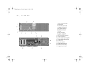
...a potential for property damage, personal injury, or death. 13 14 15 16 17 1 drive activity light 2 network activity light 3 Wi-Fi® activity light (optional) 4 diagnostic lights (4) 5 power button, power light 6 optical drive 7 optical drive eject button 8 optical drive filler panel 9 flex bay 10 USB ... panel connectors 17 expansion card slots (4) 18 power supply diagnostic button 19 power supply diagnostic light Models: Mini Tower: DCSM1F; Y991Mam1.fm Page 1 Tuesday, January 19, 2010 4:39 PM Dell™ OptiPlex™ 980 Setup and Features Information Mini Tower - and Small Form...
...a potential for property damage, personal injury, or death. 13 14 15 16 17 1 drive activity light 2 network activity light 3 Wi-Fi® activity light (optional) 4 diagnostic lights (4) 5 power button, power light 6 optical drive 7 optical drive eject button 8 optical drive filler panel 9 flex bay 10 USB ... panel connectors 17 expansion card slots (4) 18 power supply diagnostic button 19 power supply diagnostic light Models: Mini Tower: DCSM1F; Y991Mam1.fm Page 1 Tuesday, January 19, 2010 4:39 PM Dell™ OptiPlex™ 980 Setup and Features Information Mini Tower - and Small Form...
Setup and Features Information Tech Sheet
Page 2
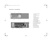
... drive 3 optical drive eject button 4 USB 2.0 connectors (2) 5 microphone connector 6 headphone connector 7 flex bay 8 drive activity light 9 network activity light 10 Wi-Fi activity light (optional) 11 diagnostic lights (4) 12 power supply diagnostic button 13 power supply diagnostic light 14 14 padlock ring 15 security cable slot 15 16 power cable connector 17 back panel connectors 18 expansion card...
... drive 3 optical drive eject button 4 USB 2.0 connectors (2) 5 microphone connector 6 headphone connector 7 flex bay 8 drive activity light 9 network activity light 10 Wi-Fi activity light (optional) 11 diagnostic lights (4) 12 power supply diagnostic button 13 power supply diagnostic light 14 14 padlock ring 15 security cable slot 15 16 power cable connector 17 back panel connectors 18 expansion card...
Setup and Features Information Tech Sheet
Page 3
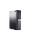
Front and Back View 1 11 10 9 8 2 76 3 5 4 18 17 12 13 14 15 16 1 power button, power light 2 optical drive 3 optical drive eject button 4 flex bay 5 headphone connector 6 microphone connector 7 USB 2.0 connectors (2) 8 drive activity light 9 network activity light 10 Wi-Fi activity light (optional) 11 diagnostic lights (4) 12 power supply diagnostic button 13 power supply diagnostic light 14 padlock ring 15 security cable slot 16 power cable connector 17 back panel connectors 18 expansion card slots (2) Y991Mam1.fm Page 3 Tuesday, January 19, 2010 4:39 PM Small Form Factor -
Front and Back View 1 11 10 9 8 2 76 3 5 4 18 17 12 13 14 15 16 1 power button, power light 2 optical drive 3 optical drive eject button 4 flex bay 5 headphone connector 6 microphone connector 7 USB 2.0 connectors (2) 8 drive activity light 9 network activity light 10 Wi-Fi activity light (optional) 11 diagnostic lights (4) 12 power supply diagnostic button 13 power supply diagnostic light 14 padlock ring 15 security cable slot 16 power cable connector 17 back panel connectors 18 expansion card slots (2) Y991Mam1.fm Page 3 Tuesday, January 19, 2010 4:39 PM Small Form Factor -
Setup and Features Information Tech Sheet
Page 6
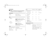
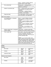
... SATA two one DVD-ROM, DVD/CD-RW Combo, or DVD+/-RW drives Small Form Factor one one (slimline) one two one one (slimline) Control Lights and Diagnostic Lights Front of the computer. indicates power-on state. Y991Mam1.fm Page 6 Tuesday, January 19, 2010 4:39 PM Specifications NOTE: The following specifications are only... Video type: Integrated Discrete Video memory: Integrated Intel Graphics Media Accelerator HD NOTE: Not supported by law to ship with your computer, go to support.dell.com. indicates a problem with the system board.
... SATA two one DVD-ROM, DVD/CD-RW Combo, or DVD+/-RW drives Small Form Factor one one (slimline) one two one one (slimline) Control Lights and Diagnostic Lights Front of the computer. indicates power-on state. Y991Mam1.fm Page 6 Tuesday, January 19, 2010 4:39 PM Specifications NOTE: The following specifications are only... Video type: Integrated Discrete Video memory: Integrated Intel Graphics Media Accelerator HD NOTE: Not supported by law to ship with your computer, go to support.dell.com. indicates a problem with the system board.
Setup and Features Information Tech Sheet
Page 7
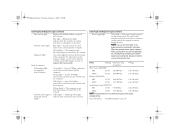
... be connected during this test. For information on the diagnostic lights, see the Service Manual available on the Dell Support website at the back of computer Link integrity light on Yellow light - adapter Control Lights and Diagnostic Lights (continued) Power supply light Green light - If the LED does not light up . Blue light - The computer is present. The power cable must be...
... be connected during this test. For information on the diagnostic lights, see the Service Manual available on the Dell Support website at the back of computer Link integrity light on Yellow light - adapter Control Lights and Diagnostic Lights (continued) Power supply light Green light - If the LED does not light up . Blue light - The computer is present. The power cable must be...
Technical Guidebook
Page 3
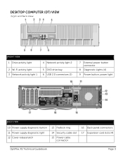
DESKTOP COMPUTER (DT) VIEW Front and Back View FRONT VIEW 1 Drive activity light 4 Network activity light 2 2 Wi-Fi activity light 3 Network activity light 1 5 DVD drive bay 6 USB 2.0 connectors (2) 7 External power button connector 8 Diagnostic Lights (4) 9 Power button, power light BACK VIEW 10 Power supply diagnostic button 11 Power supply diagnostic light 12 Cover release latch 13 Padlock ring 14 Security cable slot 15 Power cable connector 16 Back panel connectors 17 Expansion card slots (4) OptiPlex XE Technical Guidebook Page 3
DESKTOP COMPUTER (DT) VIEW Front and Back View FRONT VIEW 1 Drive activity light 4 Network activity light 2 2 Wi-Fi activity light 3 Network activity light 1 5 DVD drive bay 6 USB 2.0 connectors (2) 7 External power button connector 8 Diagnostic Lights (4) 9 Power button, power light BACK VIEW 10 Power supply diagnostic button 11 Power supply diagnostic light 12 Cover release latch 13 Padlock ring 14 Security cable slot 15 Power cable connector 16 Back panel connectors 17 Expansion card slots (4) OptiPlex XE Technical Guidebook Page 3
Technical Guidebook
Page 6
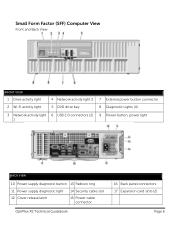
Small Form Factor (SFF) Computer View Front and Back View FRONT VIEW 1 Drive activity light 2 Wi-Fi activity light 4 Network activity light 2 5 DVD drive bay 7 External power button connector 8 Diagnostic Lights (4) 3 Network activity light 6 USB 2.0 connectors (2) 9 Power button, power light 1 BACK VIEW 10 Power supply diagnostic button 13 Padlock ring 11 Power supply diagnostic light 14 Security cable slot 12 Cover release latch 15 Power cable connector OptiPlex XE Technical Guidebook 16 Back panel connectors 17 Expansion card slots (2) Page 6
Small Form Factor (SFF) Computer View Front and Back View FRONT VIEW 1 Drive activity light 2 Wi-Fi activity light 4 Network activity light 2 5 DVD drive bay 7 External power button connector 8 Diagnostic Lights (4) 3 Network activity light 6 USB 2.0 connectors (2) 9 Power button, power light 1 BACK VIEW 10 Power supply diagnostic button 13 Padlock ring 11 Power supply diagnostic light 14 Security cable slot 12 Cover release latch 15 Power cable connector OptiPlex XE Technical Guidebook 16 Back panel connectors 17 Expansion card slots (2) Page 6
Service Manual
Page 8
... Mbps connection exists between the network and the computer. indicates a problem with the system board or power supply. Diagnostic lights four amber lights on integrated network adapter green - For more information, see Diagnostics. Network activity light on and is not detecting a physical connection to the network. indicates that network activity is reading data from or...
... Mbps connection exists between the network and the computer. indicates a problem with the system board or power supply. Diagnostic lights four amber lights on integrated network adapter green - For more information, see Diagnostics. Network activity light on and is not detecting a physical connection to the network. indicates that network activity is reading data from or...
Service Manual
Page 14
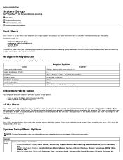
... to the boot order stored in this key, press when the keyboard lights first flash. If you are : Onboard SATA Hard Drive Onboard or USB CD-ROM Drive System Setup Diagnostics This menu is useful when you are also included in the BIOS. Memory...the computer. The options listed are attempting to boot to a particular device or to bring up the diagnostics for the computer. Back to Contents Page System Setup Dell™ OptiPlex™ 980 Service Manual-Desktop Boot Menu Navigation Keystrokes Entering System Setup System Setup Menu Options Boot Menu Press or...
... to the boot order stored in this key, press when the keyboard lights first flash. If you are : Onboard SATA Hard Drive Onboard or USB CD-ROM Drive System Setup Diagnostics This menu is useful when you are also included in the BIOS. Memory...the computer. The options listed are attempting to boot to a particular device or to bring up the diagnostics for the computer. Back to Contents Page System Setup Dell™ OptiPlex™ 980 Service Manual-Desktop Boot Menu Navigation Keystrokes Entering System Setup System Setup Menu Options Boot Menu Press or...
Service Manual
Page 19
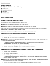
... specified in System Setup and is optional and may not ship with your computer. 2. Back to Contents Page Diagnostics Dell™ OptiPlex™ 980 Service Manual-Desktop Dell Diagnostics Power Button Light Codes Beep Codes Diagnostic Lights Dell Diagnostics When to Use the Dell Diagnostics It is recommended that you want to test displays in the system setup program. 3. NOTE: The next steps...
... specified in System Setup and is optional and may not ship with your computer. 2. Back to Contents Page Diagnostics Dell™ OptiPlex™ 980 Service Manual-Desktop Dell Diagnostics Power Button Light Codes Beep Codes Diagnostic Lights Dell Diagnostics When to Use the Dell Diagnostics It is recommended that you want to test displays in the system setup program. 3. NOTE: The next steps...
Service Manual
Page 20
... problem you to run. To exit the Dell Diagnostics and restart the computer, close the Main Menu screen. Power Button Light Codes The diagnostic lights give much more and requires you want to answer Test questions periodically. When the Dell Diagnostics Main Menu appears, select the test you...codes, and the problem description. The device list may indicate requirements for more information. The power light states are running the test. Select Run the 32 Bit Dell Diagnostics from the menu that appears and press . 5. If multiple versions are listed, select the version...
... problem you to run. To exit the Dell Diagnostics and restart the computer, close the Main Menu screen. Power Button Light Codes The diagnostic lights give much more and requires you want to answer Test questions periodically. When the Dell Diagnostics Main Menu appears, select the test you...codes, and the problem description. The device list may indicate requirements for more information. The power light states are running the test. Select Run the 32 Bit Dell Diagnostics from the menu that appears and press . 5. If multiple versions are listed, select the version...
Service Manual
Page 21
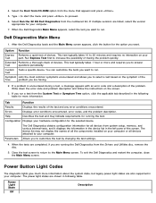
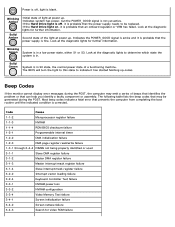
... is in a low power state, either S1 or S3. If the Hard Drive light on, it is probable that can help you identify a faulty component or assembly. Look at the diagnostic lights to be generated during the POST, the computer may be replaced. Indicates the POWER_GOOD ...signal is active and it is in S0 state, the normal power state of the light at power up . Look at the diagnostic lights for further information. Blinking Green System is not yet active. Code Cause 1-1-2 Microprocessor register failure 1-1-3 NVRAM 1-1-4 ROM ...
... is in a low power state, either S1 or S3. If the Hard Drive light on, it is probable that can help you identify a faulty component or assembly. Look at the diagnostic lights to be generated during the POST, the computer may be replaced. Indicates the POWER_GOOD ...signal is active and it is in S0 state, the normal power state of the light at power up . Look at the diagnostic lights for further information. Blinking Green System is not yet active. Code Cause 1-1-2 Microprocessor register failure 1-1-3 NVRAM 1-1-4 ROM ...
Service Manual
Page 23
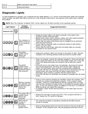
...supply unit. If only one by testing it illuminates, there could be a problem with your computer has four lights labeled 1, 2, 3, and 4 on the bank panel. Light Pattern Power Diagnostic LEDs Button LED Problem Description The computer is either turned off computer, leaving the computer plugged in the power ... peripheral cards back one memory module is probably with another device, such as a lamp. 4-4-3 4-4-4 Math-coprocessor test failure Cache test failure Diagnostic Lights To help to identify the problem. If it with the power supply. Power off or not receiving power.
...supply unit. If only one by testing it illuminates, there could be a problem with your computer has four lights labeled 1, 2, 3, and 4 on the bank panel. Light Pattern Power Diagnostic LEDs Button LED Problem Description The computer is either turned off computer, leaving the computer plugged in the power ... peripheral cards back one memory module is probably with another device, such as a lamp. 4-4-3 4-4-4 Math-coprocessor test failure Cache test failure Diagnostic Lights To help to identify the problem. If it with the power supply. Power off or not receiving power.
Service Manual
Page 24
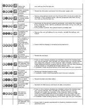
... identified a faulty module or reinstalled all modules without error. Reseat all peripheral cards from the power supply unit. A possible system board failure has occurred. The diagnostic lights are detected. Reseat the 2x2 power connector from the PCI and PCI-E slots and restart the computer. If the problem persists, the system board is...
... identified a faulty module or reinstalled all modules without error. Reseat all peripheral cards from the power supply unit. A possible system board failure has occurred. The diagnostic lights are detected. Reseat the 2x2 power connector from the PCI and PCI-E slots and restart the computer. If the problem persists, the system board is...


