Setup and Features Information Tech Sheet
Page 1
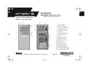
... ring 14 security cable slot 15 power cable connector 16 back panel connectors 17 expansion card slots (4) 18 power supply diagnostic button 19 power supply diagnostic light Models: Mini Tower: DCSM1F; and Small Form Factor: DCCY1F series February 2010 Y991Mam1.fm Page 1 Tuesday, January 19, 2010 4:39 PM Dell™ OptiPlex™ 980 Setup and Features Information Mini...
... ring 14 security cable slot 15 power cable connector 16 back panel connectors 17 expansion card slots (4) 18 power supply diagnostic button 19 power supply diagnostic light Models: Mini Tower: DCSM1F; and Small Form Factor: DCCY1F series February 2010 Y991Mam1.fm Page 1 Tuesday, January 19, 2010 4:39 PM Dell™ OptiPlex™ 980 Setup and Features Information Mini...
Setup and Features Information Tech Sheet
Page 2
... button 4 USB 2.0 connectors (2) 5 microphone connector 6 headphone connector 7 flex bay 8 drive activity light 9 network activity light 10 Wi-Fi activity light (optional) 11 diagnostic lights (4) 12 power supply diagnostic button 13 power supply diagnostic light 14 14 padlock ring 15 security cable slot 15 16 power cable connector 17 back panel connectors 18 expansion card slots (4)
... button 4 USB 2.0 connectors (2) 5 microphone connector 6 headphone connector 7 flex bay 8 drive activity light 9 network activity light 10 Wi-Fi activity light (optional) 11 diagnostic lights (4) 12 power supply diagnostic button 13 power supply diagnostic light 14 14 padlock ring 15 security cable slot 15 16 power cable connector 17 back panel connectors 18 expansion card slots (4)
Setup and Features Information Tech Sheet
Page 3
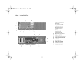
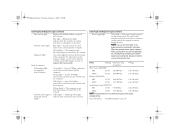
Y991Mam1.fm Page 3 Tuesday, January 19, 2010 4:39 PM Small Form Factor - Front and Back View 1 11 10 9 8 2 76 3 5 4 18 17 12 13 14 15 16 1 power button, power light 2 optical drive 3 optical drive eject button 4 flex bay 5 headphone connector 6 microphone connector 7 USB 2.0 connectors (2) 8 drive activity light 9 network activity light 10 Wi-Fi activity light (optional) 11 diagnostic lights (4) 12 power supply diagnostic button 13 power supply diagnostic light 14 padlock ring 15 security cable slot 16 power cable connector 17 back panel connectors 18 expansion card slots (2)
Y991Mam1.fm Page 3 Tuesday, January 19, 2010 4:39 PM Small Form Factor - Front and Back View 1 11 10 9 8 2 76 3 5 4 18 17 12 13 14 15 16 1 power button, power light 2 optical drive 3 optical drive eject button 4 flex bay 5 headphone connector 6 microphone connector 7 USB 2.0 connectors (2) 8 drive activity light 9 network activity light 10 Wi-Fi activity light (optional) 11 diagnostic lights (4) 12 power supply diagnostic button 13 power supply diagnostic light 14 padlock ring 15 security cable slot 16 power cable connector 17 back panel connectors 18 expansion card slots (2)
Setup and Features Information Tech Sheet
Page 6
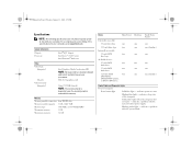
...power supply. System Information Chipset Processor Intel® Q57 chipset Intel Core™ i3/i5/i7 series Intel Pentium® dual-core Video Video type: Integrated Discrete Video memory: Integrated Intel Graphics Media Accelerator HD NOTE: Not supported by law to ship with your computer, go to support.dell....com. PCI-E x16 graphics card Upto 1759 MB (shared) NOTE: The memory shared is dependent upon the operating system and available memory. indicates power-on state. indicates sleep state of computer Power button light Solid blue light - ...
...power supply. System Information Chipset Processor Intel® Q57 chipset Intel Core™ i3/i5/i7 series Intel Pentium® dual-core Video Video type: Integrated Discrete Video memory: Integrated Intel Graphics Media Accelerator HD NOTE: Not supported by law to ship with your computer, go to support.dell....com. PCI-E x16 graphics card Upto 1759 MB (shared) NOTE: The memory shared is dependent upon the operating system and available memory. indicates power-on state. indicates sleep state of computer Power button light Solid blue light - ...
Setup and Features Information Tech Sheet
Page 7
... connection exists between the network and the computer. For information on the diagnostic lights, see the Service Manual available on the Dell Support website at the back of the computer. A good 10 Mbps connection exists between the network and the computer. A ... BTU/hr 100-240 VAC NOTE: Heat dissipation is present. Yellow light - adapter Control Lights and Diagnostic Lights (continued) Power supply light Green light - The power supply is not detecting a physical connection to the drive. Coin-cell battery 3V CR2032 lithium coin cell Diagnostic lights Four amber lights...
... connection exists between the network and the computer. For information on the diagnostic lights, see the Service Manual available on the Dell Support website at the back of the computer. A good 10 Mbps connection exists between the network and the computer. A ... BTU/hr 100-240 VAC NOTE: Heat dissipation is present. Yellow light - adapter Control Lights and Diagnostic Lights (continued) Power supply light Green light - The power supply is not detecting a physical connection to the drive. Coin-cell battery 3V CR2032 lithium coin cell Diagnostic lights Four amber lights...
Technical Guidebook
Page 3
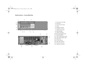
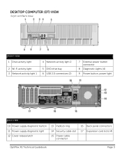
DESKTOP COMPUTER (DT) VIEW Front and Back View FRONT VIEW 1 Drive activity light 4 Network activity light 2 2 Wi-Fi activity light 3 Network activity light 1 5 DVD drive bay 6 USB 2.0 connectors (2) 7 External power button connector 8 Diagnostic Lights (4) 9 Power button, power light BACK VIEW 10 Power supply diagnostic button 11 Power supply diagnostic light 12 Cover release latch 13 Padlock ring 14 Security cable slot 15 Power cable connector 16 Back panel connectors 17 Expansion card slots (4) OptiPlex XE Technical Guidebook Page 3
DESKTOP COMPUTER (DT) VIEW Front and Back View FRONT VIEW 1 Drive activity light 4 Network activity light 2 2 Wi-Fi activity light 3 Network activity light 1 5 DVD drive bay 6 USB 2.0 connectors (2) 7 External power button connector 8 Diagnostic Lights (4) 9 Power button, power light BACK VIEW 10 Power supply diagnostic button 11 Power supply diagnostic light 12 Cover release latch 13 Padlock ring 14 Security cable slot 15 Power cable connector 16 Back panel connectors 17 Expansion card slots (4) OptiPlex XE Technical Guidebook Page 3
Technical Guidebook
Page 6
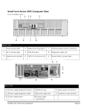
Small Form Factor (SFF) Computer View Front and Back View FRONT VIEW 1 Drive activity light 2 Wi-Fi activity light 4 Network activity light 2 5 DVD drive bay 7 External power button connector 8 Diagnostic Lights (4) 3 Network activity light 6 USB 2.0 connectors (2) 9 Power button, power light 1 BACK VIEW 10 Power supply diagnostic button 13 Padlock ring 11 Power supply diagnostic light 14 Security cable slot 12 Cover release latch 15 Power cable connector OptiPlex XE Technical Guidebook 16 Back panel connectors 17 Expansion card slots (2) Page 6
Small Form Factor (SFF) Computer View Front and Back View FRONT VIEW 1 Drive activity light 2 Wi-Fi activity light 4 Network activity light 2 5 DVD drive bay 7 External power button connector 8 Diagnostic Lights (4) 3 Network activity light 6 USB 2.0 connectors (2) 9 Power button, power light 1 BACK VIEW 10 Power supply diagnostic button 13 Padlock ring 11 Power supply diagnostic light 14 Security cable slot 12 Cover release latch 15 Power cable connector OptiPlex XE Technical Guidebook 16 Back panel connectors 17 Expansion card slots (2) Page 6
Technical Guidebook
Page 20
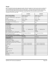
... manufacture to switch or reconfigure the PSU when alternating between 100-240VAC electrical currents/sockets. Dell recommends only Uninterruptible Power Supplies (UPS) based on PSU max wattage) 1163 3.3v CMOS battery (type and estimated battery life) Power Supply Fan 92*25mm Compliance: 1watt requirement Yes Blue Angel Compliant No Climate Savers / 80Plus ... 80*15mm Yes No Yes Yes Yes (select configurations) Yes (select configurations) Yes Yes Yes Yes Yes Yes Yes Yes Yes Yes OptiPlex XE Technical Guidebook Page 20 Power NOTE: The OptiPlex XE utilizes wide-ranging power supplies.
... manufacture to switch or reconfigure the PSU when alternating between 100-240VAC electrical currents/sockets. Dell recommends only Uninterruptible Power Supplies (UPS) based on PSU max wattage) 1163 3.3v CMOS battery (type and estimated battery life) Power Supply Fan 92*25mm Compliance: 1watt requirement Yes Blue Angel Compliant No Climate Savers / 80Plus ... 80*15mm Yes No Yes Yes Yes (select configurations) Yes (select configurations) Yes Yes Yes Yes Yes Yes Yes Yes Yes Yes OptiPlex XE Technical Guidebook Page 20 Power NOTE: The OptiPlex XE utilizes wide-ranging power supplies.
Service Manual
Page 8
... outlet. indicates a problem with the system board or power supply. indicates that the computer is not detecting a physical connection to the hard drive. Power supply light green light - When the system's power supply voltage is functional. AC power must be defective. Network activity light on the front ...test button. a good 1000 Mbps connection exists between the network and the computer. If the LED does not light up . the power supply is turned on integrated network adapter green - a good 100 Mbps connection exists between the network and the computer. off (no ...
... outlet. indicates a problem with the system board or power supply. indicates that the computer is not detecting a physical connection to the hard drive. Power supply light green light - When the system's power supply voltage is functional. AC power must be defective. Network activity light on the front ...test button. a good 1000 Mbps connection exists between the network and the computer. If the LED does not light up . the power supply is turned on integrated network adapter green - a good 100 Mbps connection exists between the network and the computer. off (no ...

Service Manual
Page 9
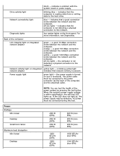
... battery 921 BTU/hr (EPA) 1235 BTU/hr (non-EPA) 100-240 VAC 3 V CR2032 lithium coin cell NOTE: Heat dissipation is calculated by using the power supply wattage rating. Physical Height Mini-tower Desktop Small form factor Width Mini-tower Desktop Small form factor Depth Mini-tower Desktop Small form factor Weight...
... battery 921 BTU/hr (EPA) 1235 BTU/hr (non-EPA) 100-240 VAC 3 V CR2032 lithium coin cell NOTE: Heat dissipation is calculated by using the power supply wattage rating. Physical Height Mini-tower Desktop Small form factor Width Mini-tower Desktop Small form factor Depth Mini-tower Desktop Small form factor Weight...

Service Manual
Page 11
Back to Contents Page Removing and Replacing Parts Dell™ OptiPlex™ 980 Service Manual-Mini-Tower Cover Drive Cover Optical Drive Hard Drive/Cage Front Panel Expansion Card Wireless Module Processor Fan Heat Sink and Processor Memory Module Internal Speaker Front Thermal Sensor Power Supply Control Panel Front I/O Panel Intrusion Switch Coin-Cell Battery System Board Back to Contents Page
Back to Contents Page Removing and Replacing Parts Dell™ OptiPlex™ 980 Service Manual-Mini-Tower Cover Drive Cover Optical Drive Hard Drive/Cage Front Panel Expansion Card Wireless Module Processor Fan Heat Sink and Processor Memory Module Internal Speaker Front Thermal Sensor Power Supply Control Panel Front I/O Panel Intrusion Switch Coin-Cell Battery System Board Back to Contents Page
Service Manual
Page 21
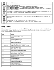
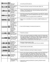
...Screen initialization failure 3-4-2 Screen retrace failure 3-4-3 Search for further information. Second state of beeps that identifies the problem or that the power supply needs to indicate it has started fetching op-codes. Most beep codes indicate a fatal error that prevents the computer from completing ...Beep Codes If the monitor cannot display error messages during the POST. The following table lists the beep codes that the power supply is in a low power state, either S1 or S3. Blinking Amber Solid Amber Initial state of a functioning machine. Solid Green System is ...
...Screen initialization failure 3-4-2 Screen retrace failure 3-4-3 Search for further information. Second state of beeps that identifies the problem or that the power supply needs to indicate it has started fetching op-codes. Most beep codes indicate a fatal error that prevents the computer from completing ...Beep Codes If the monitor cannot display error messages during the POST. The following table lists the beep codes that the power supply is in a low power state, either S1 or S3. Blinking Amber Solid Amber Initial state of a functioning machine. Solid Green System is ...
Service Manual
Page 23
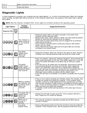
... turn off before turning off. Suggested Resolution Reseat the power cable in . Press and hold the power supply test button on the back of the power supply unit. If it to verify that the main power cable and front panel cable are turned on the bank...until you have identified a faulty module or reinstalled all internal and external peripherals, and press and hold the power supply button. Bypass power strips, power extension cables, and other power protection devices to a different DIMM connector and restart the computer. A possible system board failure has occurred....
... turn off before turning off. Suggested Resolution Reseat the power cable in . Press and hold the power supply test button on the back of the power supply unit. If it to verify that the main power cable and front panel cable are turned on the bank...until you have identified a faulty module or reinstalled all internal and external peripherals, and press and hold the power supply button. Bypass power strips, power extension cables, and other power protection devices to a different DIMM connector and restart the computer. A possible system board failure has occurred....
Service Manual
Page 24
...you find the bad one at a time) until you have identified a faulty module or reinstalled all peripheral cards from the power supply unit. Reseat the processor. If two or more memory modules are not lit after the computer successfully boots to install additional ...system board is in a normal on . If the computer starts normally, continue to install additional memory modules (one . failure has occurred. Power connector not installed properly. A possible coin cell battery failure has occurred. The computer is probably bad. A possible graphics card failure has occurred...
...you find the bad one at a time) until you have identified a faulty module or reinstalled all peripheral cards from the power supply unit. Reseat the processor. If two or more memory modules are not lit after the computer successfully boots to install additional ...system board is in a normal on . If the computer starts normally, continue to install additional memory modules (one . failure has occurred. Power connector not installed properly. A possible coin cell battery failure has occurred. The computer is probably bad. A possible graphics card failure has occurred...
Service Manual
Page 43
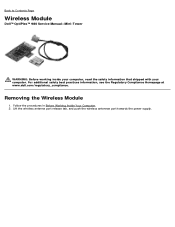
Removing the Wireless Module 1. Lift the wireless antenna port release tab, and push the wireless antennae port towards the power supply. Follow the procedures in Before Working Inside Your Computer. 2. Back to Contents Page Wireless Module Dell™ OptiPlex™ 980 Service Manual-Mini-Tower WARNING: Before working inside your computer, read the safety information that shipped with your computer. For additional safety best practices information, see the Regulatory Compliance Homepage at www.dell.com/regulatory_compliance.
Removing the Wireless Module 1. Lift the wireless antenna port release tab, and push the wireless antennae port towards the power supply. Follow the procedures in Before Working Inside Your Computer. 2. Back to Contents Page Wireless Module Dell™ OptiPlex™ 980 Service Manual-Mini-Tower WARNING: Before working inside your computer, read the safety information that shipped with your computer. For additional safety best practices information, see the Regulatory Compliance Homepage at www.dell.com/regulatory_compliance.
Service Manual
Page 65
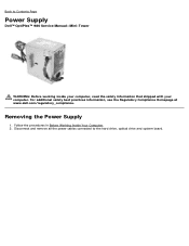
Removing the Power Supply 1. Back to the hard drive, optical drive and system board. For additional safety best practices information, see the Regulatory Compliance Homepage at www.dell.com/regulatory_compliance. Disconnect and remove all the power cables connected to Contents Page Power Supply Dell™ OptiPlex™ 980 Service Manual-Mini-Tower WARNING: Before working inside your computer, read the safety information that shipped with your computer. Follow the procedures in Before Working Inside Your Computer. 2.
Removing the Power Supply 1. Back to the hard drive, optical drive and system board. For additional safety best practices information, see the Regulatory Compliance Homepage at www.dell.com/regulatory_compliance. Disconnect and remove all the power cables connected to Contents Page Power Supply Dell™ OptiPlex™ 980 Service Manual-Mini-Tower WARNING: Before working inside your computer, read the safety information that shipped with your computer. Follow the procedures in Before Working Inside Your Computer. 2.

Service Manual
Page 66
Remove the screws that secure the power supply to the back of the computer. Disconnect the data and I/O cables from the cable holder. 4. 3.
Remove the screws that secure the power supply to the back of the computer. Disconnect the data and I/O cables from the cable holder. 4. 3.

Service Manual
Page 67
Lift the power supply up and away from the computer. 5. Press down the release latch and slide the power supply towards the front of the computer. 6.
Lift the power supply up and away from the computer. 5. Press down the release latch and slide the power supply towards the front of the computer. 6.

Service Manual
Page 68
Back to Contents Page Replacing the Power Supply To replace the power supply, perform the above steps in reverse order.
Back to Contents Page Replacing the Power Supply To replace the power supply, perform the above steps in reverse order.


