Technical Guidebook
Page 2
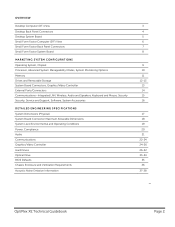
... Dimensions (Physical) System Board Connector Maximum Allowable Dimensions System Level Environmental and Operating Conditions Power, Compliance Audio Communications Graphics/Video Controller Hard Drives Optical Drive BIOS Defaults Chassis Enclosure and Ventilation Requirements Acoustic Noise Emission Information 3 4 5 6 7 8 9 10 11 12-13 13 14 15 16 17 18 19 20 21 22-24...
... Dimensions (Physical) System Board Connector Maximum Allowable Dimensions System Level Environmental and Operating Conditions Power, Compliance Audio Communications Graphics/Video Controller Hard Drives Optical Drive BIOS Defaults Chassis Enclosure and Ventilation Requirements Acoustic Noise Emission Information 3 4 5 6 7 8 9 10 11 12-13 13 14 15 16 17 18 19 20 21 22-24...
Technical Guidebook
Page 9
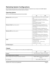
...174; Linux® (China only) FreeDOS for N-series X X Chipset NOTE: The OptiPlex XE uses a Chipset from Intel's long lifecycle Embedded Roadmap Chipset Non-volatile memory on chipset BIOS Configuration SPI (Serial Peripheral Interface) NIC EEPROM DT SFF Intel Q45 Express Chipset w/ICH10DO... 16Mbit (2MB) located at SPI_FLASH on chipset 5761-8Mbit, 57780-OTP OptiPlex XE Technical Guidebook Page 9 Marketing System ...
...174; Linux® (China only) FreeDOS for N-series X X Chipset NOTE: The OptiPlex XE uses a Chipset from Intel's long lifecycle Embedded Roadmap Chipset Non-volatile memory on chipset BIOS Configuration SPI (Serial Peripheral Interface) NIC EEPROM DT SFF Intel Q45 Express Chipset w/ICH10DO... 16Mbit (2MB) located at SPI_FLASH on chipset 5761-8Mbit, 57780-OTP OptiPlex XE Technical Guidebook Page 9 Marketing System ...
Technical Guidebook
Page 10
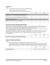
...in hardware management capabilities across platform offerings. cannot be enabled through the Dell factory; DT SFF Dell Watchdog Timer Optional via factory installation only OptiPlex XE Technical Guidebook Page 10 This functionality allows IT to address many ...issues remotely rather than having to physically visit systems. The OptiPlex™ XE supports Broadcom® TruManage™ technology which supports the following features: BIOS...
...in hardware management capabilities across platform offerings. cannot be enabled through the Dell factory; DT SFF Dell Watchdog Timer Optional via factory installation only OptiPlex XE Technical Guidebook Page 10 This functionality allows IT to address many ...issues remotely rather than having to physically visit systems. The OptiPlex™ XE supports Broadcom® TruManage™ technology which supports the following features: BIOS...
Technical Guidebook
Page 34
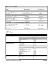
...Slots: WIFI NIC Slot: Audio: Primary Video: USB RAID On Disable Enable Enable Enable Enable Auto Auto Enable Enable Enable Enable Enable Enable Auto OptiPlex XE Technical Guidebook Page 34 Maximum Data Transfer Rates Writes N/A Reads 16x DVD/48x CD Power Source DC Power Requirements 12V, 5V DC Current ...Conditions (Non-Condensing): Operating Temperature Range -40C to 65C Relative Humidity Range 5% to 95% RH Maximum Wet Bulb Temperature 38C Altitude Range -200 to 10600m BIOS Defaults N/A 8x DVD/ 24x CD 5V 800mA 5C to 50C 20% to 80% RH 29C -200 to 3048m -40C to 65C 5% to 95%...
...Slots: WIFI NIC Slot: Audio: Primary Video: USB RAID On Disable Enable Enable Enable Enable Auto Auto Enable Enable Enable Enable Enable Enable Auto OptiPlex XE Technical Guidebook Page 34 Maximum Data Transfer Rates Writes N/A Reads 16x DVD/48x CD Power Source DC Power Requirements 12V, 5V DC Current ...Conditions (Non-Condensing): Operating Temperature Range -40C to 65C Relative Humidity Range 5% to 95% RH Maximum Wet Bulb Temperature 38C Altitude Range -200 to 10600m BIOS Defaults N/A 8x DVD/ 24x CD 5V 800mA 5C to 50C 20% to 80% RH 29C -200 to 3048m -40C to 65C 5% to 95%...
Service Manual
Page 3
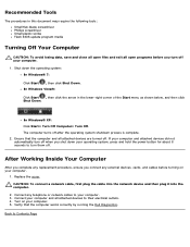
.... In Windows® XP: Click Start® Turn Off Computer® Turn Off. Ensure that the computer works correctly by running the Dell Diagnostics. Connect any external devices, cards, and cables before you turn them off. Verify that the computer and all attached devices are turned ...Start , then click the arrow in this document may require the following tools: Small flat-blade screwdriver Phillips screwdriver Small plastic scribe Flash BIOS update program media Turning Off Your Computer CAUTION: To avoid losing data, save and close all open programs before turning on your computer....
.... In Windows® XP: Click Start® Turn Off Computer® Turn Off. Ensure that the computer works correctly by running the Dell Diagnostics. Connect any external devices, cards, and cables before you turn them off. Verify that the computer and all attached devices are turned ...Start , then click the arrow in this document may require the following tools: Small flat-blade screwdriver Phillips screwdriver Small plastic scribe Flash BIOS update program media Turning Off Your Computer CAUTION: To avoid losing data, save and close all open programs before turning on your computer....
Service Manual
Page 5
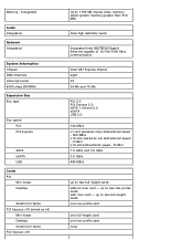
... low-profile card none up to two full-height cards without riser card - Integrated Audio Integrated Network Integrated System Information Chipset DMA channels Interrupt levels BIOS chips (NVRAM) Expansion Bus Bus type Bus speed PCI PCI Express SATA eSATA USB Cards PCI Mini-tower Desktop Small form factor PCI Express x16...
... low-profile card none up to two full-height cards without riser card - Integrated Audio Integrated Network Integrated System Information Chipset DMA channels Interrupt levels BIOS chips (NVRAM) Expansion Bus Bus type Bus speed PCI PCI Express SATA eSATA USB Cards PCI Mini-tower Desktop Small form factor PCI Express x16...
Service Manual
Page 14
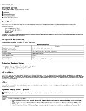
... < > -Remain in the BIOS. Making changes in the exact same order. Processor information: Displays the Processor Type, Processor Speed, Processor Bus Speed, Processor L2 cache, Processor ID, Back to Contents Page System Setup Dell™ OptiPlex™ 980 Service Manual-Desktop Boot Menu Navigation ...Keystrokes Entering System Setup System Setup Menu Options Boot Menu Press or when the Dell™ logo appears to initiate a one -time boot menu...
... < > -Remain in the BIOS. Making changes in the exact same order. Processor information: Displays the Processor Type, Processor Speed, Processor Bus Speed, Processor L2 cache, Processor ID, Back to Contents Page System Setup Dell™ OptiPlex™ 980 Service Manual-Desktop Boot Menu Navigation ...Keystrokes Entering System Setup System Setup Menu Options Boot Menu Press or when the Dell™ logo appears to initiate a one -time boot menu...
Service Manual
Page 15
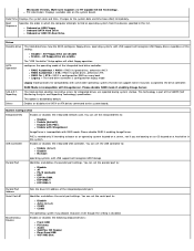
... the parallel port settings. S.M.A.R.T. This technology is disabled by default. Enables or disables the following onboard devices: Front USB PCI slots Audio OptiPlex ON Reader Rear Quad USB WiFi NIC Slot Date/Time Displays the system date and time. Drives Enables or disables the SATA or ATA... drive controller. Onboard or USB Floppy Onboard SATA Hard Drive Onboard or USB CD-Rom Drive Drives Diskette drive This field determines how the BIOS configures floppy drives, operating systems with ImageServer. You can set the serial port to: Disable Auto (default) COM1 COM3 The operating system...
... the parallel port settings. S.M.A.R.T. This technology is disabled by default. Enables or disables the following onboard devices: Front USB PCI slots Audio OptiPlex ON Reader Rear Quad USB WiFi NIC Slot Date/Time Displays the system date and time. Drives Enables or disables the SATA or ATA... drive controller. Onboard or USB Floppy Onboard SATA Hard Drive Onboard or USB CD-Rom Drive Drives Diskette drive This field determines how the BIOS configures floppy drives, operating systems with ImageServer. You can set the serial port to: Disable Auto (default) COM1 COM3 The operating system...
Service Manual
Page 18
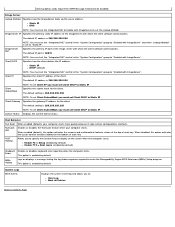
...Static IP DHCP (default) Client IP NOTE: You must set the "Integrated NIC" control in the "System Configuration" group to enter the Manageability Engine BIOS Extensions(MEBx) Setup program. ImageServer Port Specifies the primary IP port of the ImageServer with which the client software communicates. Specifies the static IP address... DHCP to "Enabled with ImageServer to "Static IP". Image Server Lookup Method Specifies how the ImageServer looks up the server address. System Logs BIOS Events Displays the system event log and allows you must set the Lookup Method.
...Static IP DHCP (default) Client IP NOTE: You must set the "Integrated NIC" control in the "System Configuration" group to enter the Manageability Engine BIOS Extensions(MEBx) Setup program. ImageServer Port Specifies the primary IP port of the ImageServer with which the client software communicates. Specifies the static IP address... DHCP to "Enabled with ImageServer to "Static IP". Image Server Lookup Method Specifies how the ImageServer looks up the server address. System Logs BIOS Events Displays the system event log and allows you must set the Lookup Method.
Service Manual
Page 21
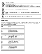
...supply is fine. Solid Green System is in S0 state, the normal power state of light at power up . The BIOS will turn the light to this state to indicate it has started fetching op-codes. The following table lists the beep codes... signal is active and it is probable that an onboard regulator or VRM has failed. Code Cause 1-1-2 Microprocessor register failure 1-1-3 NVRAM 1-1-4 ROM BIOS checksum failure 1-2-1 Programmable interval timer 1-2-2 DMA initialization failure 1-2-3 DMA page register read/write failure 1-3-1 through 2-4-4 DIMMs not being properly identified or...
...supply is fine. Solid Green System is in S0 state, the normal power state of light at power up . The BIOS will turn the light to this state to indicate it has started fetching op-codes. The following table lists the beep codes... signal is active and it is probable that an onboard regulator or VRM has failed. Code Cause 1-1-2 Microprocessor register failure 1-1-3 NVRAM 1-1-4 ROM BIOS checksum failure 1-2-1 Programmable interval timer 1-2-2 DMA initialization failure 1-2-3 DMA page register read/write failure 1-3-1 through 2-4-4 DIMMs not being properly identified or...
Service Manual
Page 22
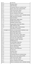
... port test failure 4-4-2 Failure to decompress code to shadowed memory 4-4-3 Math coprocessor test failure 4-4-4 Cache test failure 1-1-2 Microprocessor register failure 1-1-3 NVRAM read/write failure 1-1-4 ROM BIOS checksum failure 1-2-1 Programmable interval timer failure 1-2-2 DMA initialization failure 1-2-3 DMA page register read/write failure 1-3 Video Memory Test failure 1-3-1 through 2-4-4 Memory not being properly identified...
... port test failure 4-4-2 Failure to decompress code to shadowed memory 4-4-3 Math coprocessor test failure 4-4-4 Cache test failure 1-1-2 Microprocessor register failure 1-1-3 NVRAM read/write failure 1-1-4 ROM BIOS checksum failure 1-2-1 Programmable interval timer failure 1-2-2 DMA initialization failure 1-2-3 DMA page register read/write failure 1-3 Video Memory Test failure 1-3-1 through 2-4-4 Memory not being properly identified...
Service Manual
Page 23
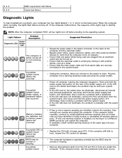
...Button LED Problem Description The computer is operating normally but a memory power failure has occurred. Memory modules are securely connected to the system board. BIOS may be corrupt or missing. NOTE: After the computer completes POST, all peripheral cards from the system board, then press and hold the ...power extension cables, and other power protection devices to verify that the main power cable and front panel cable are detected, but the BIOS may be with the system board. A possible system board failure has occurred. Allow one module and restart the computer.
...Button LED Problem Description The computer is operating normally but a memory power failure has occurred. Memory modules are securely connected to the system board. BIOS may be corrupt or missing. NOTE: After the computer completes POST, all peripheral cards from the system board, then press and hold the ...power extension cables, and other power protection devices to verify that the main power cable and front panel cable are detected, but the BIOS may be with the system board. A possible system board failure has occurred. Allow one module and restart the computer.


